[0010]In accordance with a one aspect of the present inventions, an implant assembly comprises an elongated pusher member, and an implantable device (e.g., a vaso-occlusive device) mounted to the distal end of the pusher member. The implant assembly further comprises an electrolytically severable joint disposed on the pusher member, wherein the implantable device detaches from the pusher member when the severable joint is severed. The implant assembly further comprises a return
electrode carried by the distal end of the pusher member in proximity to, but electrically isolated from, the severable joint. For example, the return
electrode may take the form of a coil disposed about the pusher member. The return electrode may be carried by the pusher member in such a manner that it remains with the implantable device or remains the pusher member when the severable joint is severed. The implant assembly further comprises a terminal carried by the proximal end of the pusher member in electrical communication with the severable joint. The use of a return electrode on the pusher member decreases the effective distance between the anodic severable joint and cathodic return electrode, thereby decreasing the detachment time and increasing the reliability,
repeatability, and uniformity of the detachment process.
[0017]The implant assembly further comprises a terminal carried by the proximal end of the pusher member in electrical communication with the severable joint. The implant assembly further comprises an
electrically conductive path extending between the terminal and one of the severable joint and the return electrode, wherein the
electrically conductive path includes the
electrically conductive sheath. The use of the electrically conductive sheath increases the conductance of the electrically conductive path between the terminal and the severable joint or return electrode, as compared to the case where a standard
electrical conductor or the stiffening member is used without the electrically conductive sheath.
[0029]In one embodiment, the insulative sheath is configured to prevent
diffusion of an
electrolyte from a detachment region between the severable joint and the return electrode. In this manner, the electrically insulative sheath may maintain the ideal electrolytic environment within the detachment region between the severable joint and the return electrode in order to facilitate detachment of the implant assembly. In one embodiment, one or both of the severable joint and the return electrode has a
hydrophilic coating, so as to, e.g., facilitate wicking of an electrolyte within the detachment region when desired.
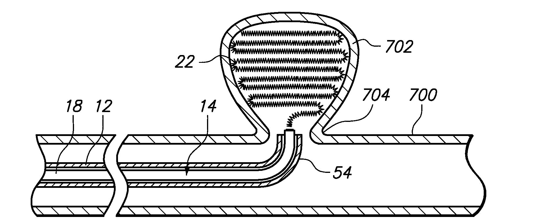
[0032]The method further comprises introducing the
medical device within the patient via a pusher member (e.g., through a delivery
catheter), and substantially preventing the electrolyte from being diffused away from the detachment region using an electrically insulative sheath. In one embodiment, the insulative sheath is fixably coupled to the pusher member. The method further comprises conveying electrical energy (e.g., direct
electrical current) to a joint disposed on the pusher member, and conveying electrical energy from a return electrode carried by the pusher member (e.g., a coil disposed about the pusher member) to induce an electrolytic reaction between the joint and the return electrode. As a result of the electrolytic reaction, the joint is severed to detach the
medical device from the pusher member at a
target site (e.g., an aneurismal sac) within the patient. In one method, the pusher member is removed from the patient.
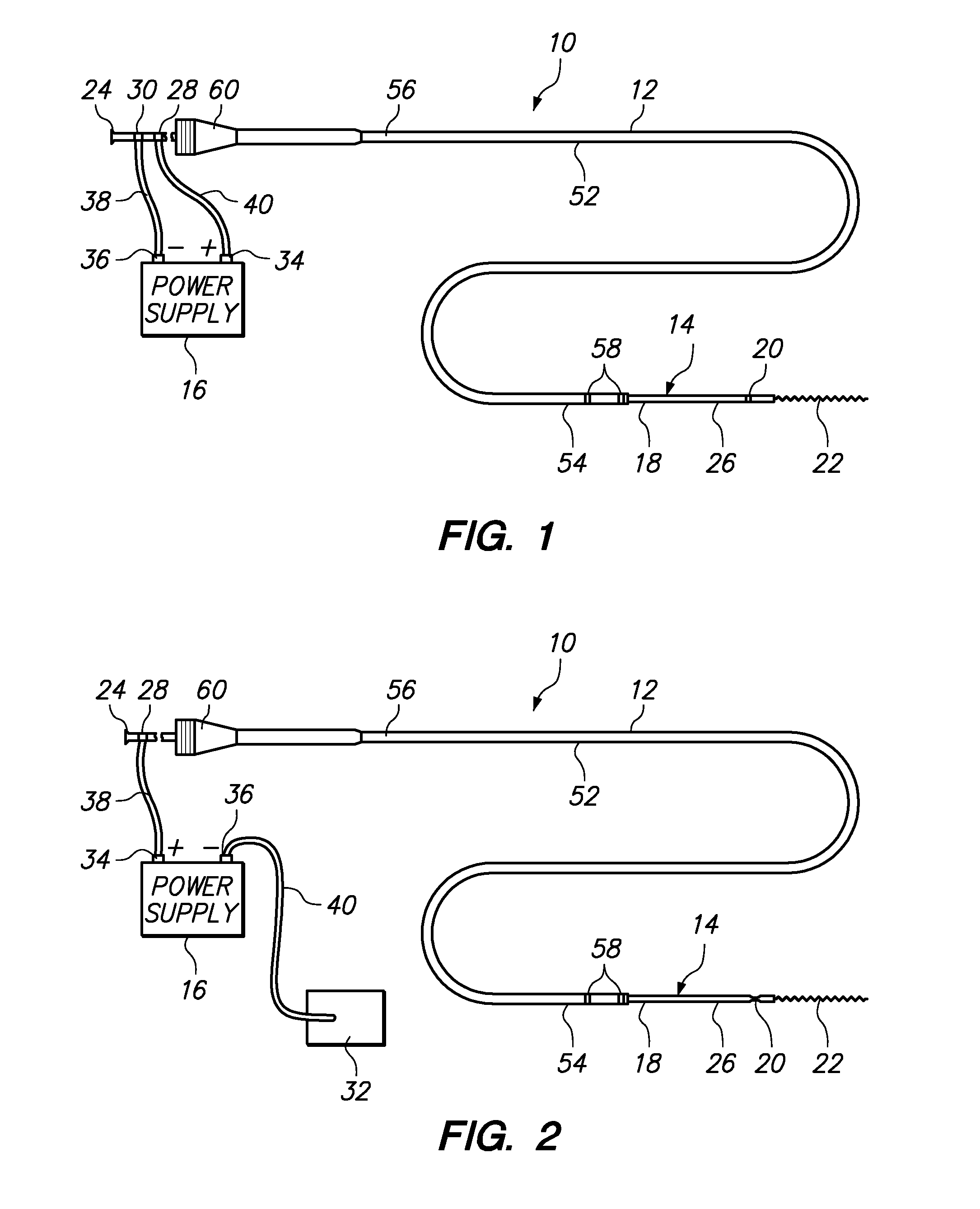
[0033]In accordance with yet another aspect of the present inventions, a medical
system comprises an implant assembly that includes an elongated pusher member, an implantable device (e.g., a vaso-occlusive device) mounted to the distal end of the pusher member, and an electrolytically severable joint disposed on the pusher member, wherein the implantable device detaches from the pusher member when the severable joint is severed. The medical
system further comprises an electrical power supply coupled to the implant assembly, the power supply configured for conveying pulsed electrical energy (e.g., direct
electrical current) to the severable joint. By way of non-limiting example, the pulsed electrical energy may have a
duty cycle within the range of 5 percent to 20 percent, and a frequency in the range of 5 KHz to 20 KHz. Pulsing the electrical energy delivered to the severable joint will tend to decrease the detachment time and increase the reliability,
repeatability, and uniformity of the detachment process.
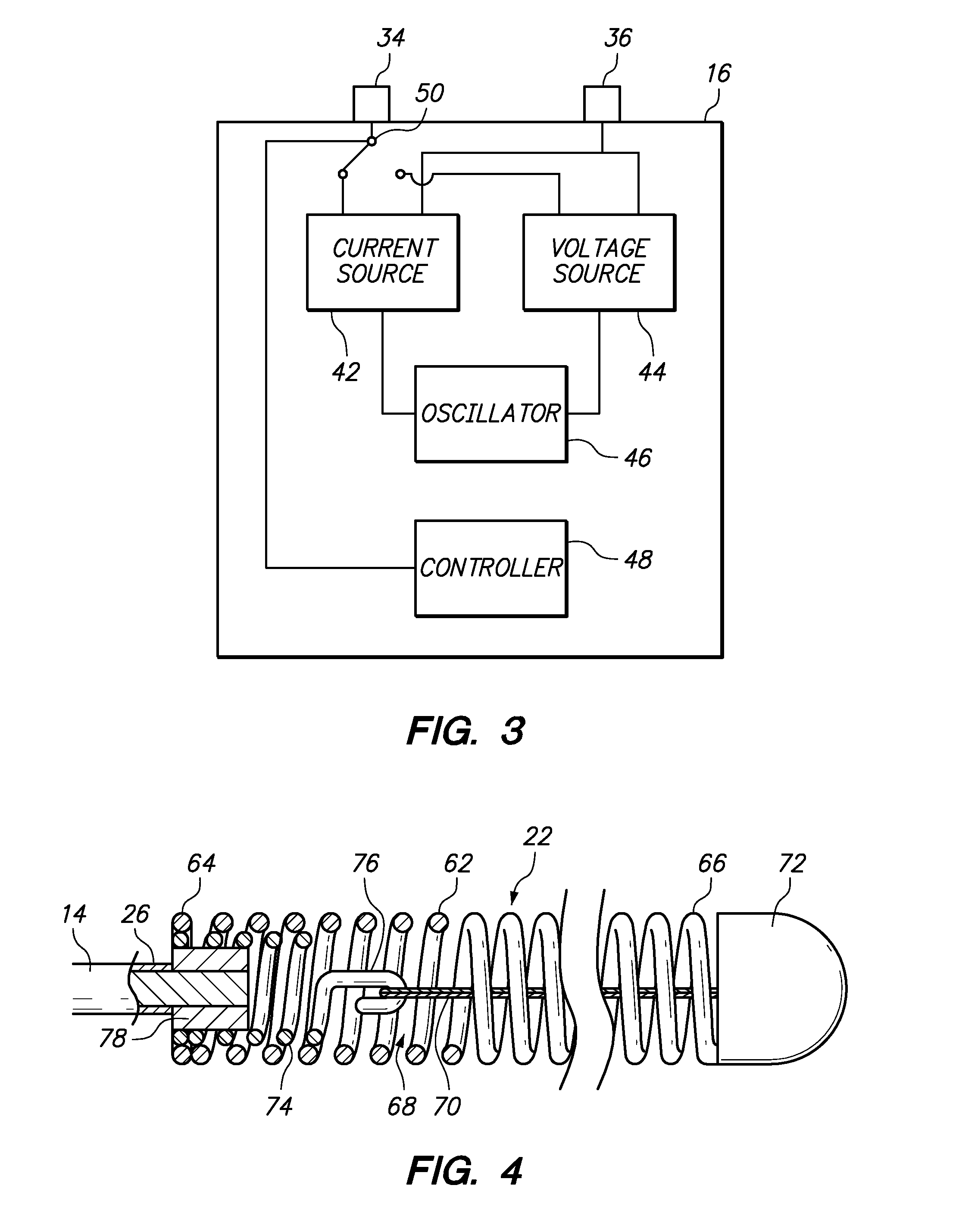
[0039]The initial electrical energy from the
constant current source may quickly break through the
oxide layer on the severable joint, whereas the electrical energy from the
constant voltage source may minimize bubbling at the detachment region, thereby decreasing the detachment time and increasing the reliability,
repeatability, and uniformity of the detachment process.

