
Method and system for a glitch correction in an all digital phase lock loop

a technology of all digital phase and glitch correction, applied in the field of all digital phase lock loop glitch correction, can solve the problems of phase signal being off, fractional phase signal and integer phase signal being misaligned, fractional phase signal and integer phase signal being problematic, etc., to increase the energy efficiency of the phase lock loop and reduce the number of glitches

Inactive Publication Date: 2012-07-17
PANASONIC CORP
View PDF7 Cites 11 Cited by
  • Summary
  • Abstract
  • Description
  • Claims
  • Application Information

AI Technical Summary

Benefits of technology

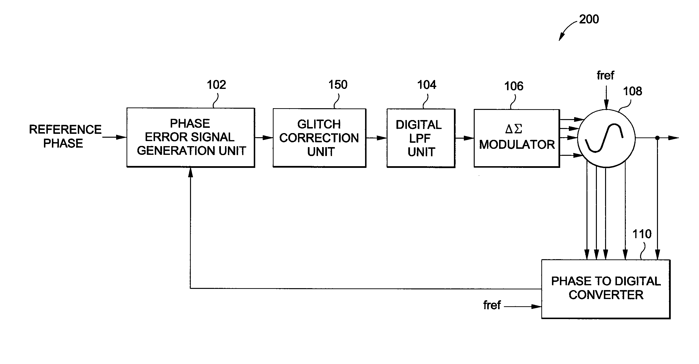
[0009]The glitch correction unit can remove the glitches in the phase error signal. The glitch correction unit can analyze the difference between consecutive phase error data to determine if the difference is greater than a predetermined phase error threshold. If the difference is greater than a predetermined phase error threshold, then one of the predetermined phase error data contains a glitch and a lookup table can be used to determine a subtraction value. The subtraction value can be subtracted from the consecutive phase error data containing the glitch to correct the phase error data.
[0012]In addition, the phase lock loop can also include a phase rotator and a calibration block. The calibration block can be connected to the glitch correction unit and the phase rotator. The calibration block can determine the number of glitches in the phase error signal for a predetermined period of time for each phase rotation of the multi-phase signal. The calibration block can instruct the phase rotator to rotate the multi-phase signal from the multi-phase oscillator by a plurality of phase rotations and generate a glitch graph mapping the number of glitches for a particular phase rotation. Using the glitch graph, the calibration block can determine which phase rotation generates the minimum number of glitches and can therefore instruct the phase rotator to rotate the multi-phase signal by the phase rotation which generates the minimum number of glitches. This can reduce the number of glitches in the phase error signal.
[0013]In addition, the glitch correction unit, the integer phase generation portion of the phase to digital converter (counter), and / or the calibration block can be selectively activated or deactivated in order to increase energy efficiency of the phase lock loop.

Problems solved by technology

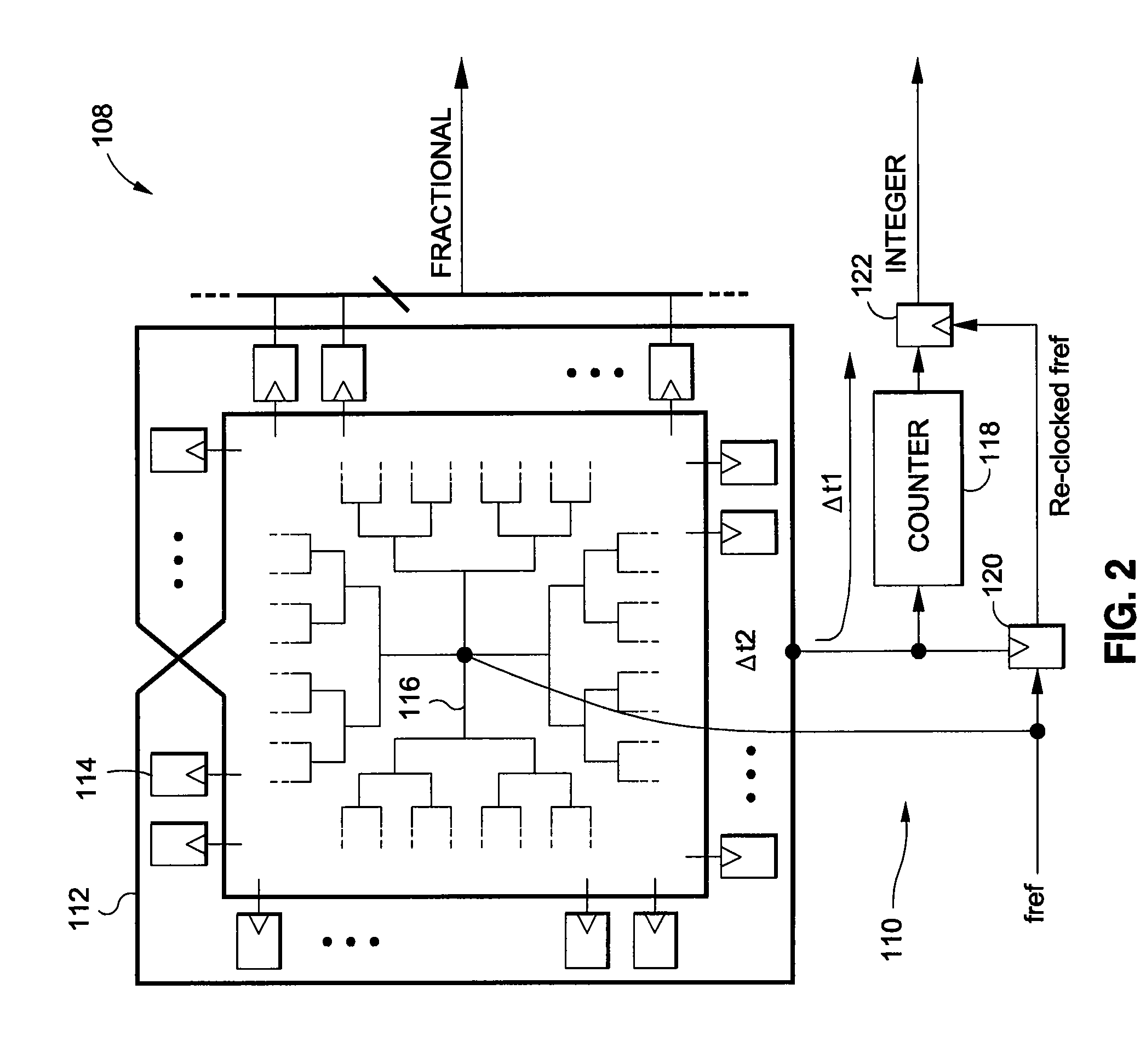
This can result in the fractional phase signal and the integer phase signal being misaligned.
The misalignment in the fractional phase signal and the integer phase signal can be problematic since the sum is used to generate the phase signal.
This leads to the phase signal being off by the increment of the integer phase signal since the integer phase signal was prematurely incremented for a short period of time.
Such glitches in the phase signal are propagated through to the phase error signal and can reduce the efficiency and / or the performance of the phase lock loop.
In addition, the phase lock loop may encounter problems when attempting to remain in compliance with a specification, such as those propagated by the 3rd Generation Partnership Project (“3GPP”).

Method used


Image

  • Method and system for a glitch correction in an all digital phase lock loop
  • Method and system for a glitch correction in an all digital phase lock loop
  • Method and system for a glitch correction in an all digital phase lock loop

Examples


Embodiment Construction

[0045]Reference will now be made in detail to the preferred embodiments of the invention which set forth the best modes contemplated to carry out the invention, examples of which are illustrated in the accompanying drawings. While the invention will be described in conjunction with the preferred embodiments, it will be understood that they are not intended to limit the invention to these embodiments. On the contrary, the invention is intended to cover alternatives, modifications and equivalents, which may be included within the spirit and scope of the invention as defined by the appended claims. Furthermore, in the following detailed description of the present invention, numerous specific details are set forth in order to provide a thorough understanding of the present invention. However, it will be obvious to one of ordinary skill in the art that the present invention may be practiced without these specific details. In other instances, well known methods, procedures, components, mo...


PUM


Abstract

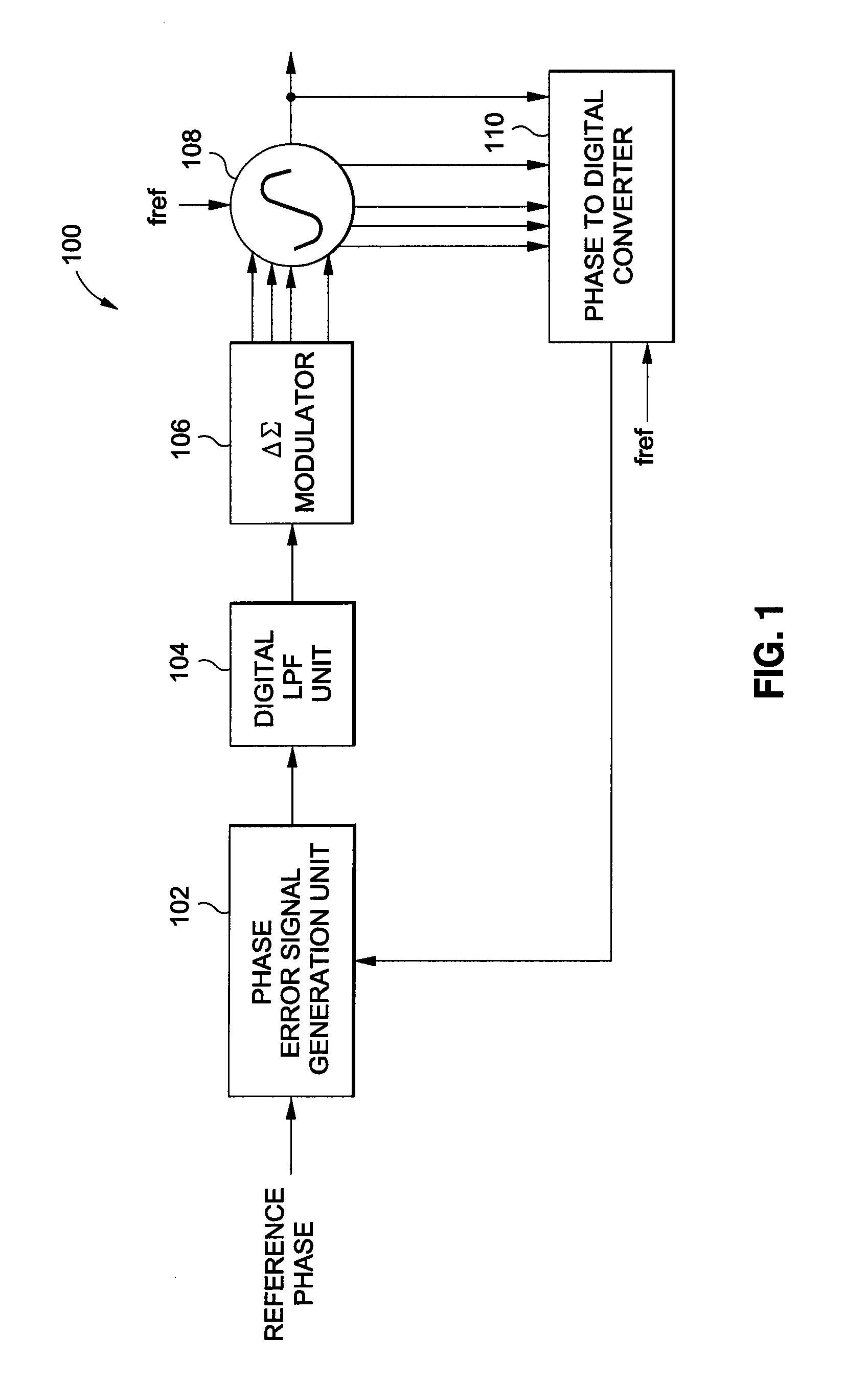
The present invention relates to a method and system for glitch correction in an all digital phase lock loop. An all digital phase lock loop can include a phase error signal generation unit, a multi-phase oscillator, a glitch correction unit, and a phase to digital converter. The phase to digital converter receives a multi-phase signal from the multi-phase oscillator and generates a phase signal. The error signal generation unit receives the phase signal and a reference phase signal and generates a phase error signal, which is fed to the glitch correction unit. The glitch correction unit removes the glitches in the phase error signal by a portion of the phase error signal. The phase lock loop can also include a phase rotator and a calibration block. The calibration block instructs the phase rotator to rotate the multi-phase signal by the phase rotation which generates the minimum number of glitches.

Description

BACKGROUND[0001]1. Field of the Invention[0002]The present invention relates to a method and system for glitch correction in an all digital phase lock loop.[0003]2. Description of Related Art[0004]Conventional all digital phase lock loops utilizing a multi-phase oscillator generate a fractional phase signal and an integer phase signal which are summed to form a phase signal. The phase signal is compared with a reference phase signal and the difference is taken to determine a phase error signal. However, in generating the fractional phase signal and the integer phase signal, conventional phase lock loops can have two different paths.[0005]The two different paths can have different delay times in generating the fractional phase signal or the integer phase signal when clocked by a reference clock signal. This can result in the fractional phase signal and the integer phase signal being misaligned. The misalignment in the fractional phase signal and the integer phase signal can be proble...

Claims


Application Information

Patent Timeline
Patent Type & Authority Patents(United States)
IPC IPC(8): H03L7/06
CPCH03L7/16H03L2207/50
Inventor TAKINAMI, KOJISTRANDBERG, RICHARDLIANG, PAUL CHENG-PO
Owner PANASONIC CORP
Learn More