Multi-bend steerable mapping catheter

a mapping catheter and multi-bend technology, applied in the field of electrophysiology (“ ep”) mapping catheters, can solve the problems of ineffective pumping of blood through the heart, blockage of mapping catheters extending across the isthmus, interference with ablation catheters, etc., and achieves the effect of facilitating prolapsing and increasing hardness

Active Publication Date: 2012-07-24
BOSTON SCI SCIMED INC
View PDF48 Cites 32 Cited by
  • Summary
  • Abstract
  • Description
  • Claims
  • Application Information

AI Technical Summary

Benefits of technology

[0010]The catheter shaft comprising a soft outer tubing that has an embedded reinforcing braid extending from the handle through a main body section of the catheter to increase its hardness. The reinforcing braid terminates in a transition region between the main body section and the prolapsing section, so that the outer shaft of the prolapsing section is much softer, facilitating its prolapsing against the HRA. The distal section may be steered bi-directionally by actuating pull wires (e.g., using a steering mechanism in the catheter handle) having distal ends attached to opposing sides of a flat, resilient center support member positioned in an interior of the distal section. The steering assembly also includes a tightly wound, highly flexible compression coil that extends from the handle to the support member through a central lumen of the outer shaft, with the pull wires positioned within an inner lumen of the flexible coil. To facilitate prolapsing of, and provide structural support to, the prolapsing section, the cross-section of the compression coil changes from generally circular to generally oval or “flattened” within the prolapsing section, prior to the transition to the distal section.

Problems solved by technology

AF results from abnormal electrical impulses propagating through aberrant myocardial tissue pathways, which leads to ineffective pumping of the blood through the heart, as well as other complications.
For example, because it passes across the lower atrial chamber, maneuvering the mapping catheter for achieving proper electrical contact in the HRA can be difficult.
Further, since most ablation catheters used for AFL and AF interventional procedures are inserted through the groin and inferior vena cava (IVC), and are maneuvered to ablate tissue in the isthmus region of the lower atrial chamber, the mapping catheter extending across the isthmus can block and interfere with the ablation catheter.
Plus, the patient and attending physician must cope with having two different access ports into the patient's venous system (i.e., both through the jugular and through the groin), making simultaneous control of the respective mapping and ablation catheters more difficult, and increasing the chances of related complications and patient discomfort.
The loop portion extends over the isthmus region in the lower right atrium (LRA), interfering with the ablation catheter, and the limited penetration of the CS results in corresponding limited CS mapping data.

Method used


Image

  • Multi-bend steerable mapping catheter
  • Multi-bend steerable mapping catheter
  • Multi-bend steerable mapping catheter

Examples


Embodiment Construction

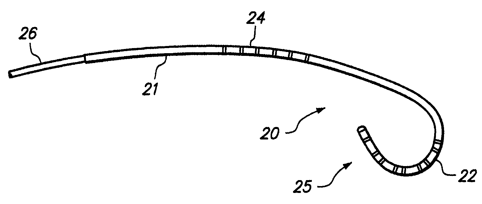
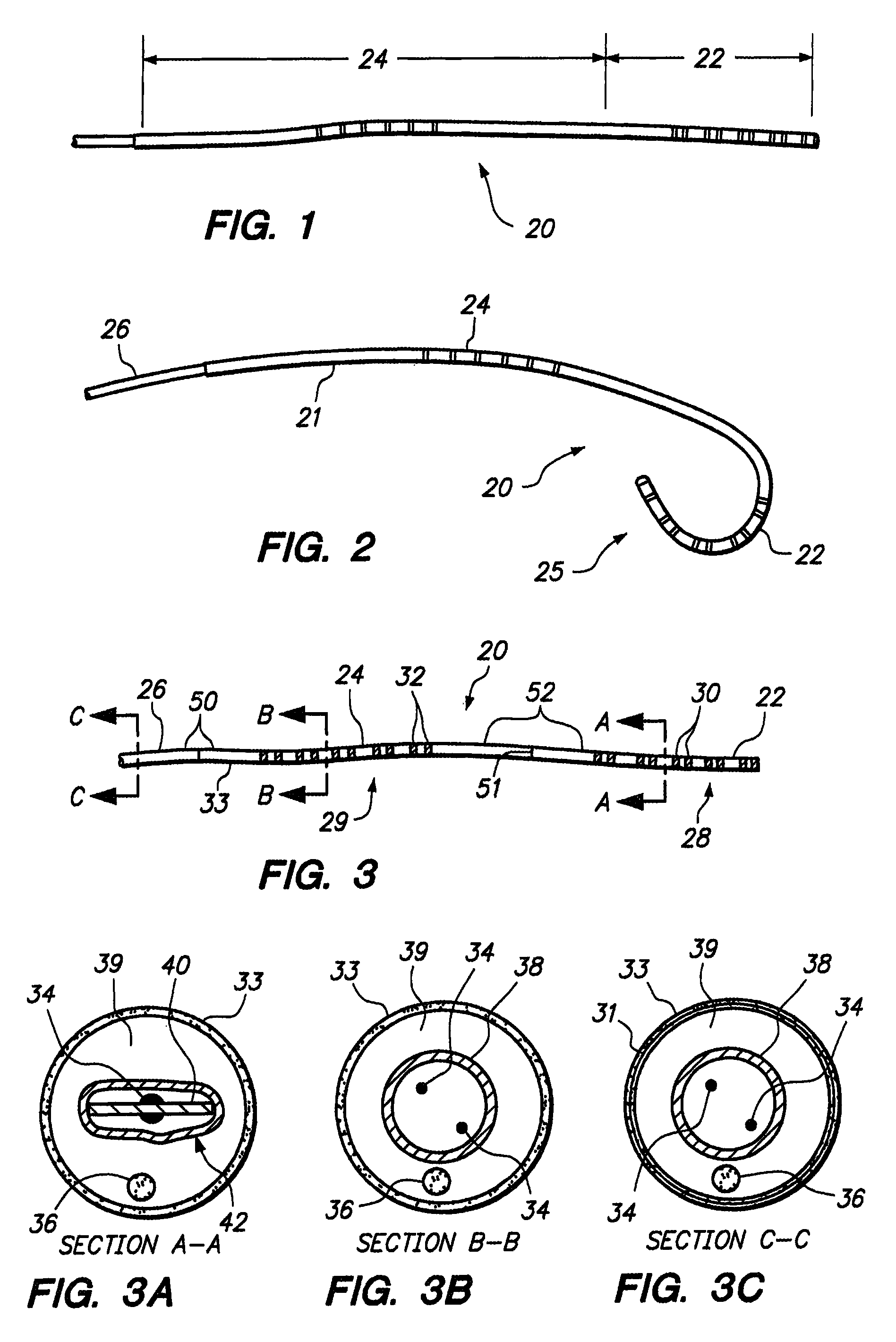
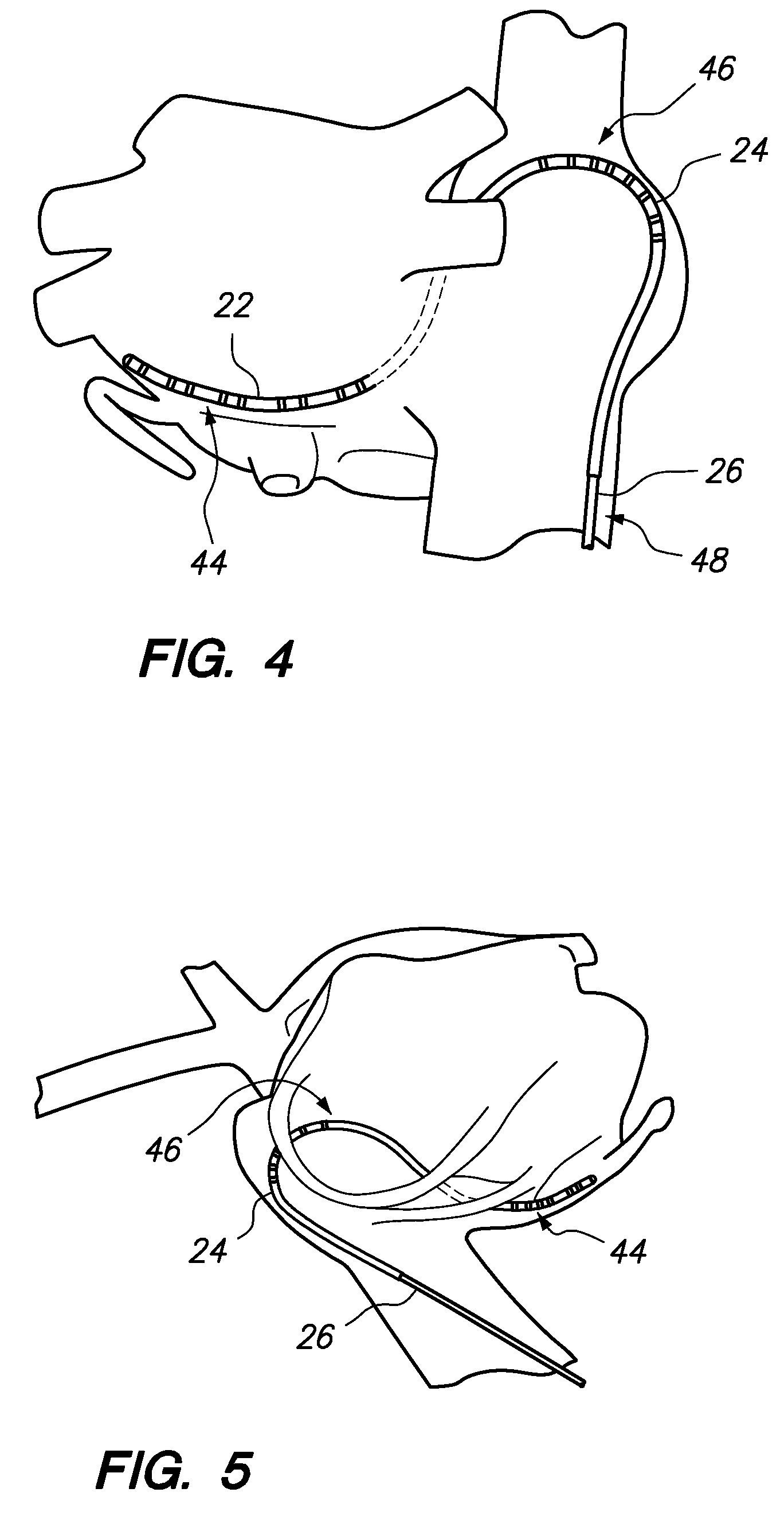
[0022]FIG. 1 depicts a distal portion of a diagnostic catheter 20 constructed in accordance with one embodiment of the invention. The catheter 20 comprises an elongate, flexible shaft 21 extending from a proximal handle (not shown), as is well-known in the art for electrophysiology catheters. The catheter shaft 21 generally includes a steerable distal section 22, and a prolapsing section 24 located immediately proximal of the distal section 20, which distal and prolapsing sections 22 and 24 are sized and configured for placement in a patient's coronary sinus (CS) and high right atrium (HRA), respectively. As best seen in FIG. 3, the catheter 20 is a “twenty pole” catheter, with ten electrodes 28 (comprising five electrode pairs 30) carried on the steerable distal section 22 for mapping in the CS, and another ten electrodes 29 (comprising five electrode pairs 32) carried on the prolapsing section 24 for mapping the HRA. The electrodes 28, 29 are coupled to respective lead wires that ...


PUM


Abstract

An electrophysiology catheter introduced through the groin and inferior vena cava into the right side of the heart comprises an elongate flexible shaft having a steerable distal section and a prolapsing section located proximally of the distal section. The distal section is inserted into the coronary sinus and a back-steering force is applied to the catheter to anchor the distal section therein, after which the catheter is further advanced to prolapse the prolapsing section against the high right atrium. Electrical pathways in both the coronary sinus and the high right atrium are mapped using respective electrode pairs carried on the distal and prolapsing sections of the catheter.

Description

RELATED APPLICATION DATA[0001]The present application is a continuation of U.S. patent application Ser. No. 11 / 470,132, filed Sep. 5, 2006, now U.S. Pat. No. 7,740,039, the priority of which is claimed under 35 U.S.C. §120, and the contents of which is incorporated herein by reference in its entirety, as though set forth in full.FIELD OF INVENTION[0002]This invention pertains to electrophysiology (“EP”) mapping catheters and, more particularly, to a multi-bend, steerable catheter configured for accessing and mapping the high right atrium and coronary sinus via groin access and the superior vena cava.BACKGROUND[0003]Electrophysiology is the study of electrical impulses through the heart and is focused primarily on diagnosing and treating arrhythmias, conditions in which electrical impulses within the heart vary from the normal rate or rhythm of a heartbeat. The most common arrhythmia is atrial fibrillation (AF), which is characterized by rapid, disorganized contractions of the heart'...

Claims


Application Information

Patent Timeline
Patent Type & Authority Patents(United States)
IPC IPC(8): A61B5/04A61B5/296A61B5/332A61B5/361
CPCA61B5/0422A61B5/6852A61B5/042A61M25/0147A61B5/287A61B5/027A61B5/283
Inventor KOBLISH, JOSEF V.
Owner BOSTON SCI SCIMED INC
Why Eureka
Try Eureka