Electronic endoscope system

a technology of electronic endoscope and endoscope, which is applied in the field of electronic endoscope systems, can solve the problems of one frame difference in exposure timing between the first and second exposure, use more power, and deformation of image quality, so as to prevent image deformation and simplify the structure of electronic endoscop

Active Publication Date: 2012-07-31
FUJIFILM CORP
View PDF25 Cites 53 Cited by
  • Summary
  • Abstract
  • Description
  • Claims
  • Application Information

AI Technical Summary

Benefits of technology

[0009]Another object of the present invention is to provide an electronic endoscope system having a simple structure and convenient operation.
[0018]Turning off the light source during the readout of the image signals results in synchronizing the exposure timing of all the pixels even with the rolling shutter technique. The rolling shutter artifact, or the deformation of image is thereby prevented without using of a mechanical shutter or the like. As a result, the structure of the electronic endoscope is simplified.
[0019]By switching between the first and second imaging modes, it is possible to obtain an appropriate image for every diagnostic examination and treatment. In addition, the images two different kinds can be displayed next to each other. Therefore, the electronic endoscope system becomes more convenient than ever.

Problems solved by technology

Moreover, the pixel amplifiers differ in performance, and may cause a particular noise to degrade the image quality.
The CCD image sensor, by contrast, can produce high-sensitivity, high-resolution images although it uses more power and has structure-inherent problems such as smear and blooming.
However, the CMOS sensors use the rolling shutter, which causes one frame difference in exposure timing between the first and last horizontal lines.
Each frame results to have the horizontal lines exposed under different illumination conditions, it is impossible to obtain the images of different illumination conditions successively.

Method used


Image

  • Electronic endoscope system
  • Electronic endoscope system
  • Electronic endoscope system

Examples


Embodiment Construction

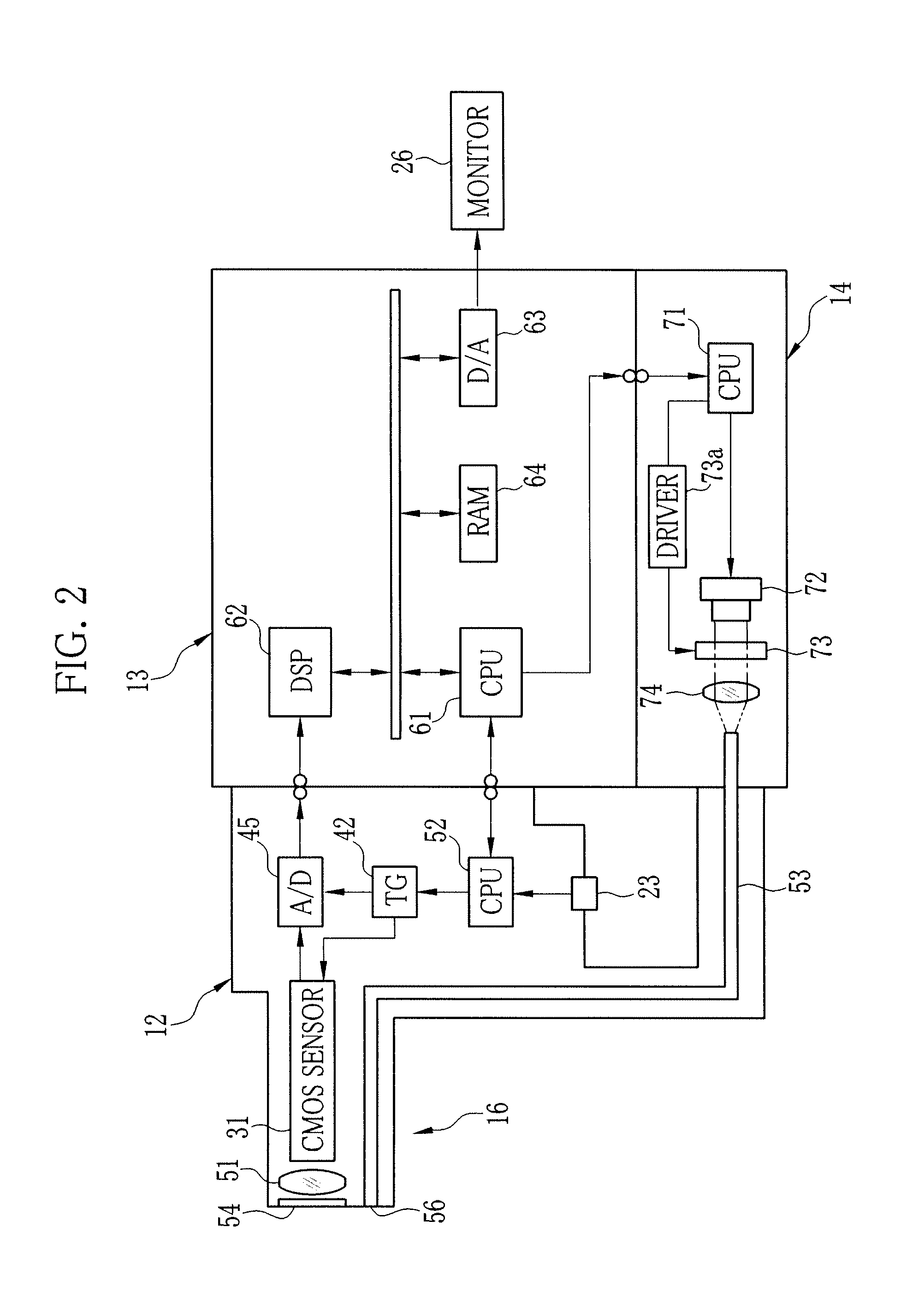
[0027]Referring to FIG. 1, an electronic endoscope system 11 includes an electronic endoscope (hereinafter, endoscope) 12, a processing device 13 and a light source device 14. The endoscope 12 is composed of an insertion section 16 to be inserted into a patient's body, a handling section 17 connected to a proximal end of the insertion section 16, and a universal cord 18. The insertion section 16 includes a long and slender flexible portion 20, a bending portion 19 and a distal portion 16a, and is able to bend in any directions to assume the shape of a tubular passage in the body.

[0028]The bending portion 19 is connected to a rear end of the distal portion 16a. The bending portion 19 is composed of a plurality of annular joint pieces pivotally linked to one another, and coupled to an angle knob 21 on the handling section 17 via a tensioning wire (not shown) running through the insertion section 16. The bending portion 19 bends up, down, right and left as the angle knob is rotated to ...


PUM


Abstract

An electronic endoscope system includes an electronic endoscope having a CMOS image sensor on the tip of an insertion section, a light source device for illuminating the interior of a patient's body, and a processing device for reading out image signals from the CMOS image sensor. The electronic endoscope system can operate with a standard imaging mode and a special imaging mode. When the time taken to read out the image signals from all the pixels in the standard mode is defined as T, the light source device in the special imaging mode emits illumination light in every first half period T / 2 while switching a wavelength of the illumination light between two different wavebands. In every second half period T / 2, the processing device reads out the image signals from the half of the pixels.

Description

FIELD OF THE INVENTION[0001]The present invention relates generally to electronic endoscope systems, and more particularly to an electronic endoscope system for visualizing the interior of a patient's body using a CMOS image sensor while changing the waveband of illumination light.BACKGROUND OF THE INVENTION[0002]In the field of medicine, electronic endoscope systems are widely used. In a diagnostic procedure using the electronic endoscope system, an electronic endoscope is inserted into a body cavity of a patient to capture an image of an internal body part using a miniature image sensor provided at a tip of a slender insertion section. Some of the recent endoscope systems have an ability to switch the wavelength of illumination light for lighting the internal body part between several wavebands (see, United State Patent Application Publications No. 2008 / 0043469 A1 and No. 2006 / 0198620 A1). To the body tissue or structure difficult to observe under white visible light (hereinafter,...

Claims


Application Information

Patent Timeline
Patent Type & Authority Patents(United States)
IPC IPC(8): A61B1/04A61B1/06
CPCA61B1/0005A61B1/045A61B1/0638A61B5/0062H04N5/2354H04N5/343H04N5/3456A61B1/05A61B5/0084H04N5/374H04N2005/2255A61B1/0646A61B1/0655H04N23/555H04N25/42H04N25/445H04N23/74H04N25/76
Inventor ENDO, AZUCHITAKAMATSU, MASAKITAKAHASHI, YASUFUMINISHIDA, KAZUHIROKIDO, TAKASHIHASEGAWA, HIROYUKIOHTA, YASUNORI
Owner FUJIFILM CORP
Why Eureka
Try Eureka