

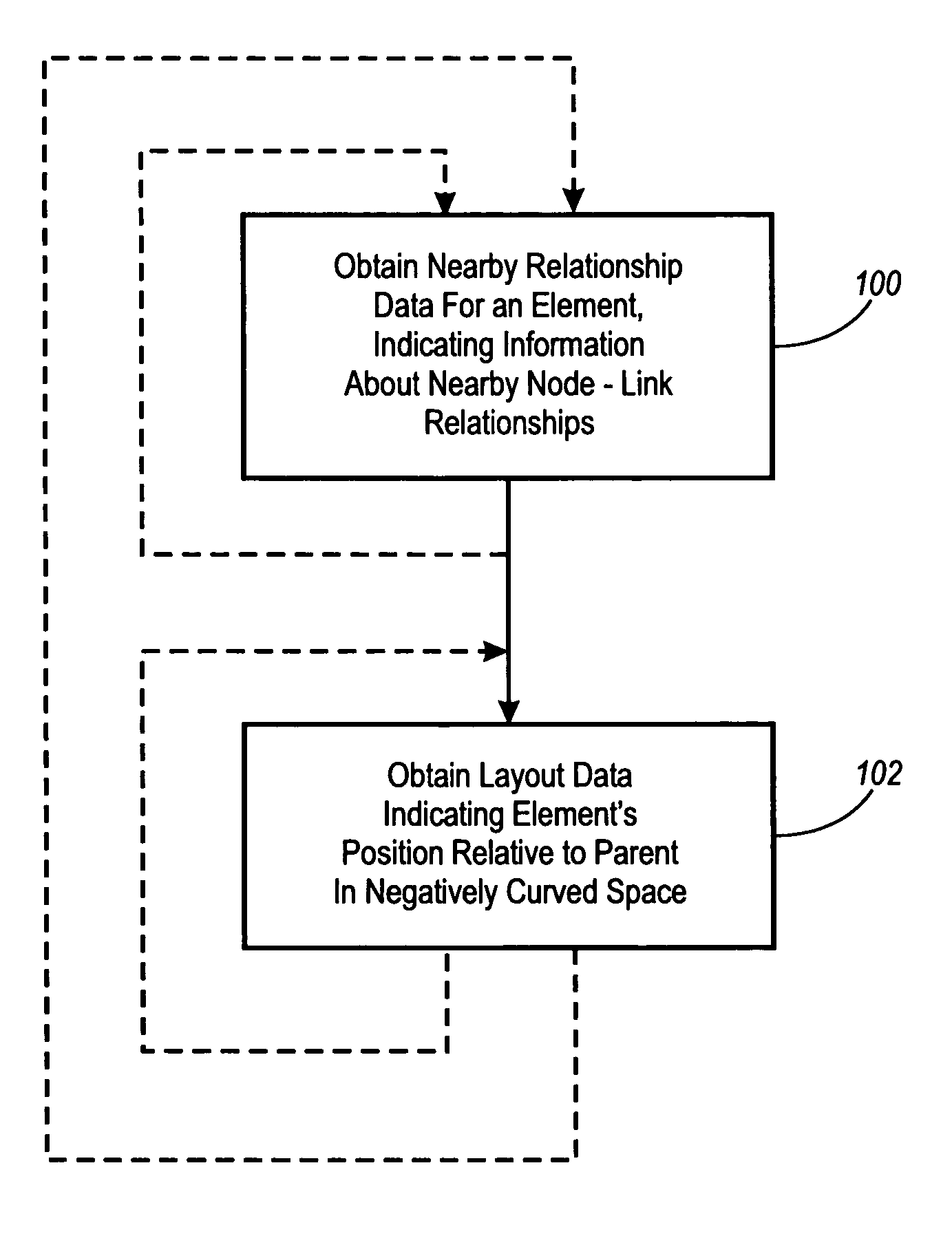
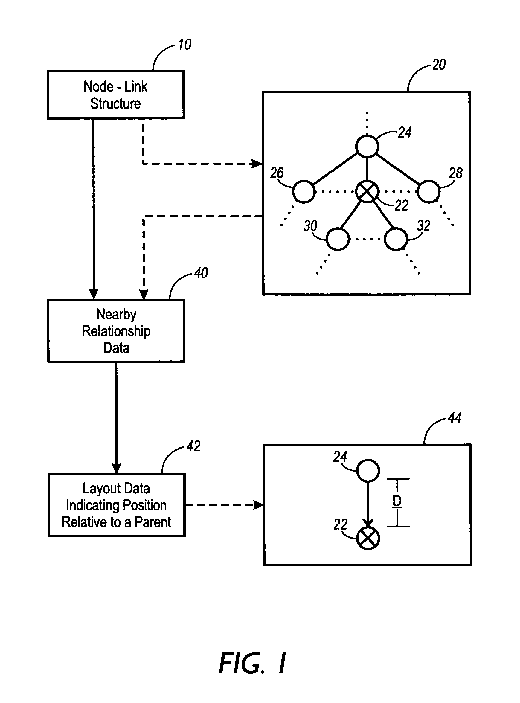
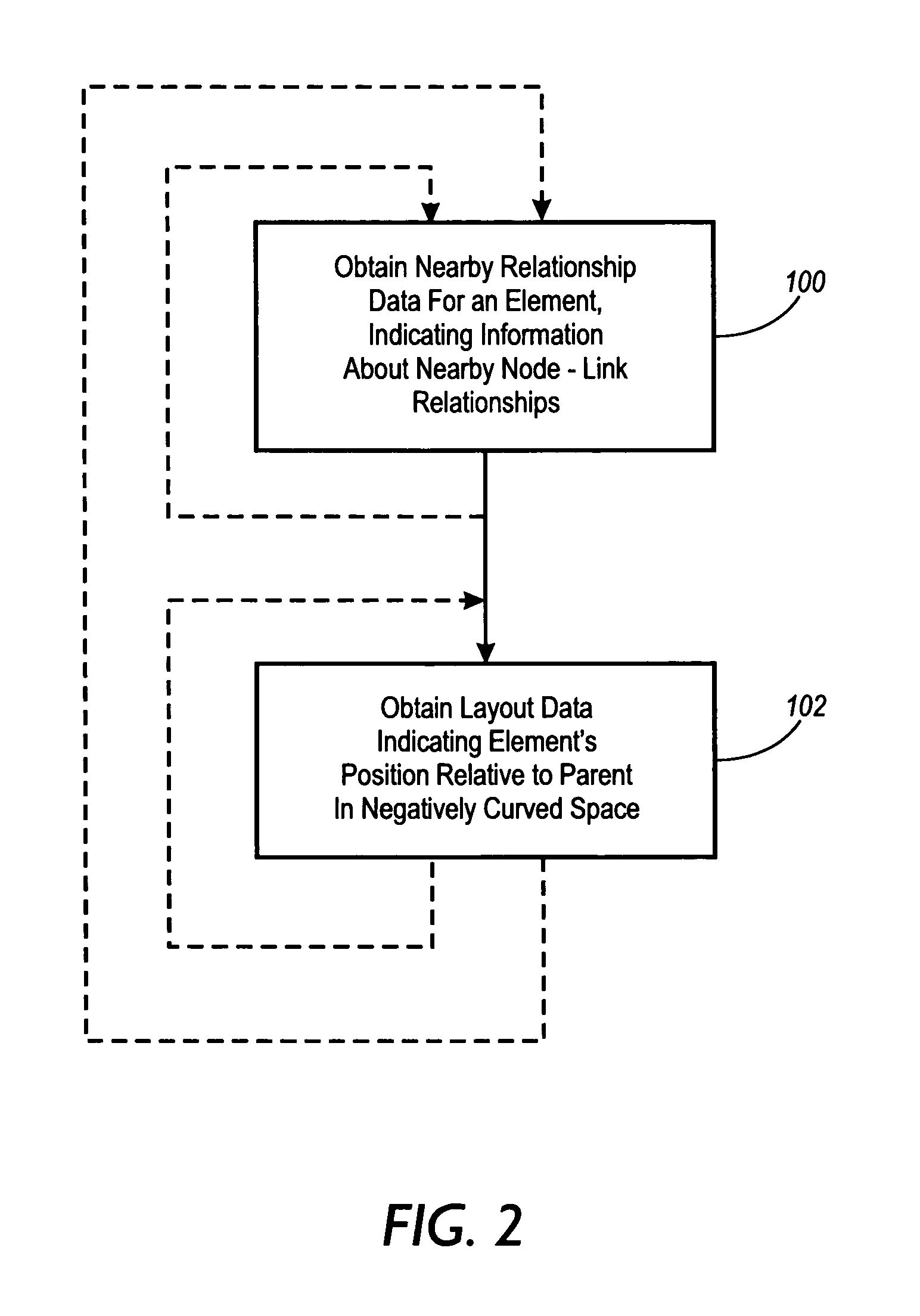
Local relative layout of node-link structures in space with negative curvature
a node-link structure and space technology, applied in static indicating devices, 2d-image generation, instruments, etc., can solve the problems of slow layout on a large structure, preventing a user from effectively interacting with the changed structure, etc., to achieve adequate precision, improve animation performance, and simplify animation algorithms
- Summary
- Abstract
- Description
- Claims
- Application Information
AI Technical Summary
Benefits of technology
Problems solved by technology
Method used
Image

Examples
Embodiment Construction
A. Conceptual Framework
[0026]The following conceptual framework, when taken with the conceptual frameworks set forth in U.S. Pat. Nos. 5,590,250 and 5,619,632, incorporated herein by reference, is helpful in understanding the broad scope of the invention, and the terms defined below have the indicated meanings throughout this application, including the claims.
[0027]A “node-link structure” is a structure that includes items that can be distinguished into nodes and links, with each link relating two or more of the nodes. A “graph” is a node-link structure in which each link relates two nodes. A “directed graph” is a graph in which each link indicates direction between the nodes it relates, with one node being a source or “from-node” of the link and the other being a destination or “to-node” of the link. An “acyclic directed graph” is a directed graph in which the links, when followed in their indicated directions, do not provide a path from any node back to itself. A “tree” is an acyc...
PUM
 Abstract
Description
Claims
Application Information