Scissoring-type current-perpendicular-to-the-plane giant magnetoresistance (CPP-GMR) sensors with damped free layer structures

a technology of free layer structure and cpp-gmr, which is applied in the field of cpp-gmr sensors, can solve the problems of limiting the bias current at which the sensors can operate, prone to current-induced noise and instability, and substantial low-frequency magnetic nois

Active Publication Date: 2012-07-31
WESTERN DIGITAL TECH INC
View PDF16 Cites 14 Cited by
  • Summary
  • Abstract
  • Description
  • Claims
  • Application Information

AI Technical Summary

Problems solved by technology

CPP-GMR sensors are susceptible to current-induced noise and instability.
This can produce continuous gyrations of the magnetization, resulting in substantial low-frequency magnetic noise if the bias current is above a certain level.
However, the adverse effect of STT limits the bias current at which the sensors can operate.
However, magnetic damping of the free layer in a CPP-GMR sensor does not address the STT problem associated with the pinned layer.
However, a scissoring-type CPP-GMR sensor is still susceptible to STT, which limits the bias current density and thus the sensitivity of the sensor.
In addition to STT-induced instability, a scissoring-type CPP-GMR sensor is susceptible to magnetic instability from a different source.
In situations where the signal field is antiparallel to the bias field, the total applied field on the scissoring-type sensor is reduced in magnitude (in particular that originating at track edges), and the sensor is more susceptible to magnetic instability than a spin-valve type sensor where the total applied field on the sensor is never smaller than the hard bias field (which is strongest at the track edges).
This generally makes the stabilization of the scissoring-type sensor more difficult compared to a spin-valve sensor.

Method used


Image

  • Scissoring-type current-perpendicular-to-the-plane giant magnetoresistance (CPP-GMR) sensors with damped free layer structures
  • Scissoring-type current-perpendicular-to-the-plane giant magnetoresistance (CPP-GMR) sensors with damped free layer structures
  • Scissoring-type current-perpendicular-to-the-plane giant magnetoresistance (CPP-GMR) sensors with damped free layer structures

Examples


Embodiment Construction

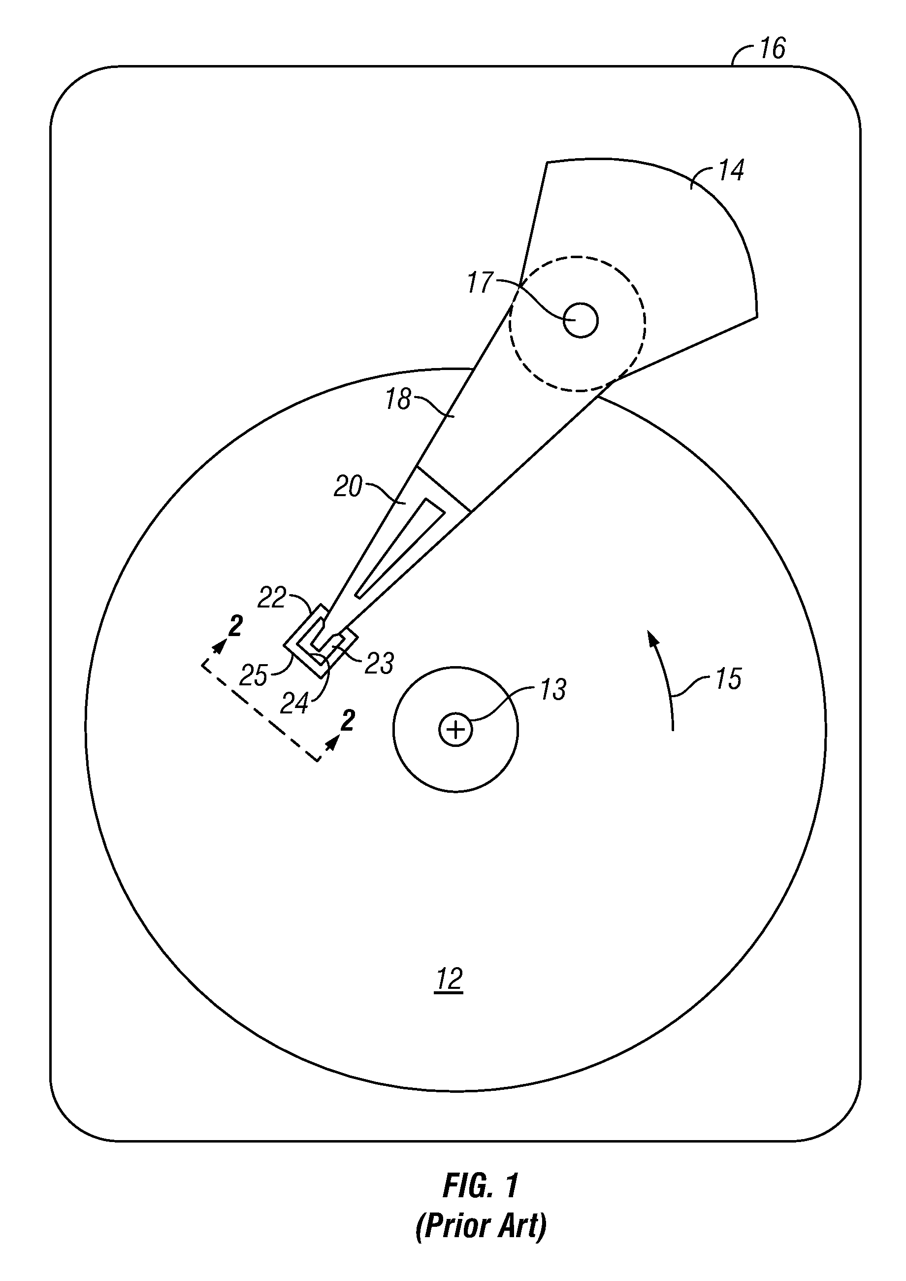
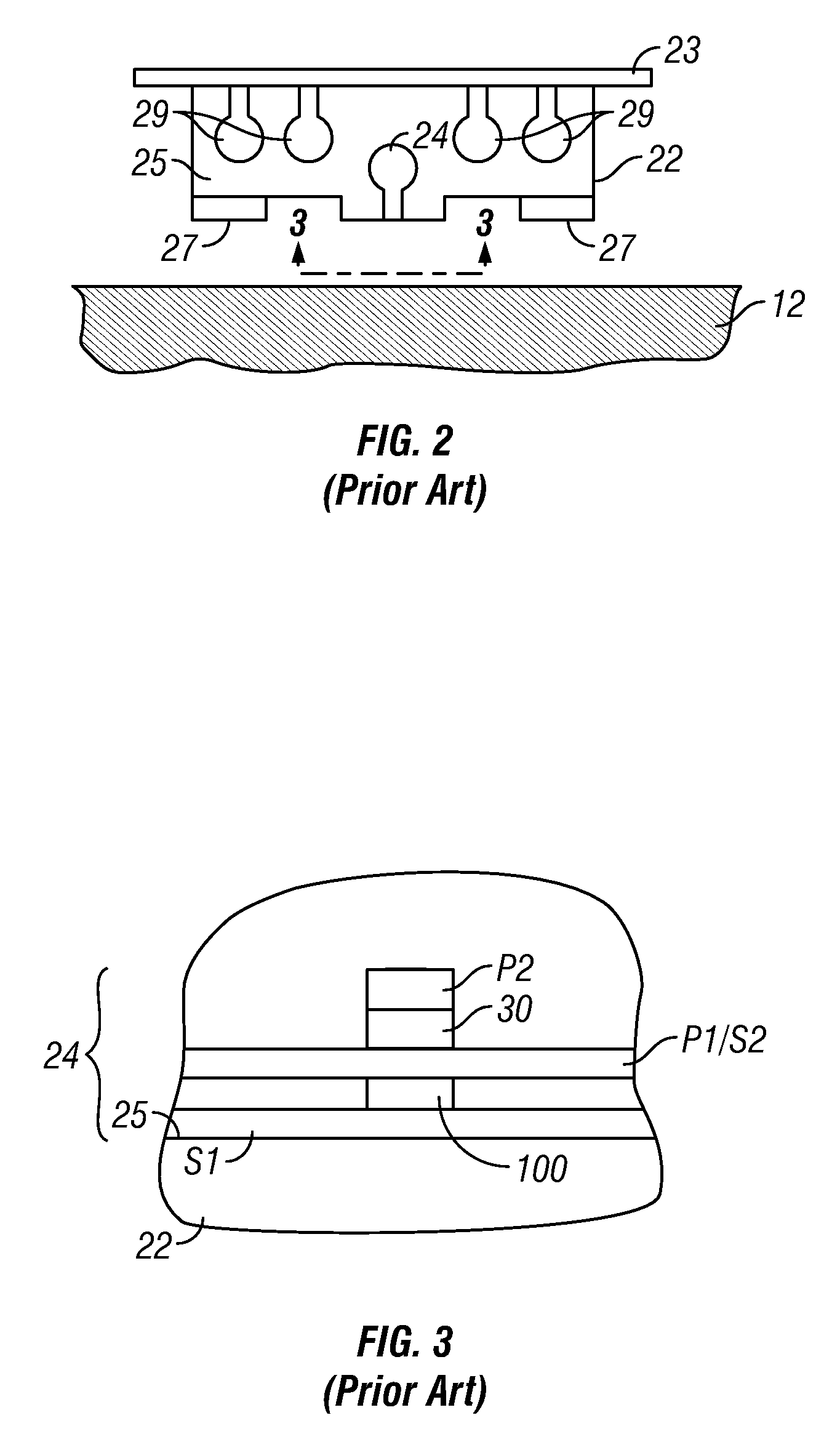
[0023]The CPP magnetoresistive (MR) sensor of this invention has application for use in a magnetic recording disk drive, the operation of which will be briefly described with reference to FIGS. 1-3. FIG. 1 is a block diagram of a conventional magnetic recording hard disk drive. The disk drive includes a magnetic recording disk 12 and a rotary voice coil motor (VCM) actuator 14 supported on a disk drive housing or base 16. The disk 12 has a center of rotation 13 and is rotated in direction 15 by a spindle motor (not shown) mounted to base 16. The actuator 14 pivots about axis 17 and includes a rigid actuator arm 18. A generally flexible suspension 20 includes a flexure element 23 and is attached to the end of arm 18. A head carrier or air-bearing slider 22 is attached to the flexure 23. A magnetic recording read / write head 24 is formed on the trailing surface 25 of slider 22. The flexure 23 and suspension 20 enable the slider to “pitch” and “roll” on an air-bearing generated by the r...


PUM

PropertyMeasurementUnit
resistanceaaaaaaaaaa
diameteraaaaaaaaaa
critical currentaaaaaaaaaa

Abstract

A “scissoring-type” current-perpendicular-to-the-plane giant magnetoresistive (CPP-GMR) sensor has magnetically damped free layers. In one embodiment each of the two free layers is in contact with a damping layer that comprises Pt or Pd, or a lanthanoid (an element selected from the group consisting of La, Ce, Pr, Nd, Pm, Sm, Eu, Gd, Tb, Dy, Ho, Er, Th, Yb, and Lu). Each of the two free layers has one of its surfaces in contact with the sensor's electrically conducting nonmagnetic spacer layer and its other surface in contact with its associated damping layer. A nonmagnetic film may be located between each free layer and its associated damping layer. In another embodiment the damping element is present as a dopant or impurity in each of the two free layers. In another embodiment a nanolayer of the damping element is located within each of the two free layers.

Description

BACKGROUND OF THE INVENTION[0001]1. Field of the Invention[0002]The invention relates generally to a current-perpendicular-to-the-plane (CPP) sensor based on the giant magnetoresistance (GMR) effect that operates with the sense current directed perpendicularly to the planes of the layers making up the sensor stack, and more particularly to a scissoring-type CPP-GMR sensor with dual sensing or free layers.[0003]2. Background of the Invention[0004]One type of conventional magnetoresistive sensor used as the read head in magnetic recording disk drives is a sensor based on the giant magnetoresistance (GMR) effect. A GMR sensor has a stack of layers that includes two ferromagnetic layers separated by a nonmagnetic electrically conductive spacer layer, which is typically copper (Cu). In one type of GMR sensor, called a “spin-valve”, one of the ferromagnetic layer has its magnetization direction fixed, such as by being pinned by exchange coupling with an adjacent antiferromagnetic layer, a...

Claims


Application Information

Patent Timeline
Patent Type & Authority Patents(United States)
IPC IPC(8): G11B5/33
CPCB82Y10/00B82Y25/00G11B5/3929G11B5/3932G11B2005/3996
Inventor CAREY, MATTHEW J.CHILDRESS, JEFFREY R.MAAT, STEFANSMITH, NEIL
Owner WESTERN DIGITAL TECH INC
Why Eureka
Try Eureka