
System and method for amplifying low level signals provided on electrical supply power

a low-level signal and electrical supply technology, applied in the direction of amplifiers with semiconductor devices only, amplifiers with semiconductor devices, transducer details, etc., can solve the problems of limiting signal bandwidth, voltage levels high enough to damage circuit components in many applications, and the inability to simply amplify the received signal and safely use downstream, etc., to achieve the effect of minimal signal distortion and reduced signal bandwidth

Active Publication Date: 2012-07-31
FIBERPLEX TECH
View PDF26 Cites 4 Cited by
  • Summary
  • Abstract
  • Description
  • Claims
  • Application Information

AI Technical Summary

Benefits of technology

[0007]It is an object of the present invention to provide an amplifier for an information carrying signal provided on electrical supply power, which amplifies the signal to desired levels with minimal reduction in signal bandwidth and minimal signal distortion.
[0008]It is another object of the present invention to provide an amplifier for a low level signal superimposed on electrical supply power which safely amplifies just the low level signal while preserving high signal fidelity.
[0009]It is yet another object of the present invention to provide an amplifier for a low level signal superimposed on electrical supply power whose implementation is simple and highly cost effective.

Problems solved by technology

Because these signals are superimposed on the more significant phantom power levels, the composite received signal cannot simply be amplified and safely used downstream.
The resulting voltage levels would be high enough to damage circuit components in many applications.
Among the significant drawbacks of this approach are that it limits signal bandwidth and tends to introduce signal distortion.
The prohibitively high costs of such transformers typically require design tradeoffs which accede to the limited bandwidth and unwanted signal distortion of less-than-optimal transformer coupling.

Method used


Image

  • System and method for amplifying low level signals provided on electrical supply power
  • System and method for amplifying low level signals provided on electrical supply power
  • System and method for amplifying low level signals provided on electrical supply power

Examples


Embodiment Construction

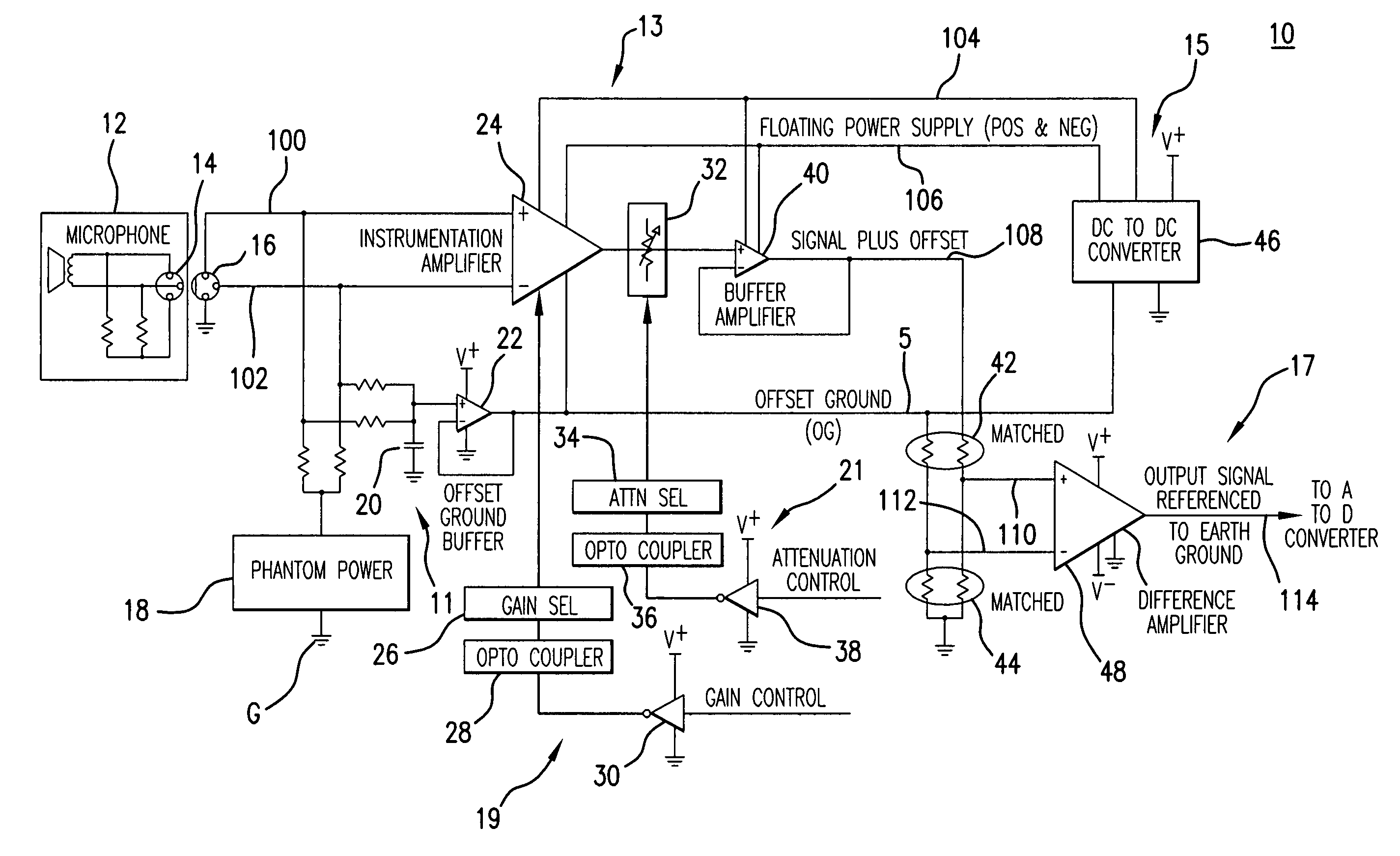
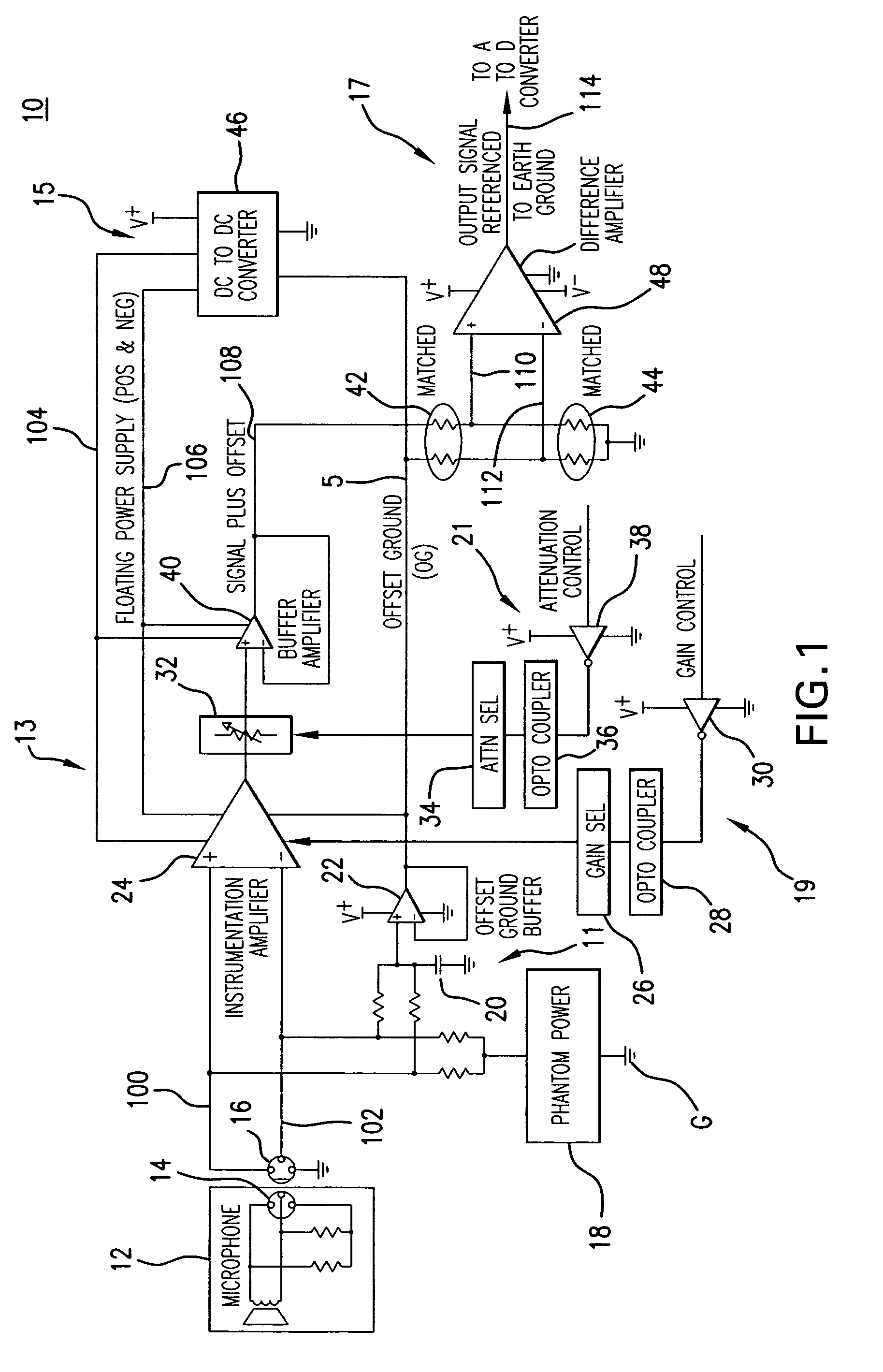
[0016]Referring now to FIG. 1, there is shown a schematic diagram illustrating a circuit employed in a system formed in accordance with one exemplary embodiment of the present invention. Generally, system 10 is configured in this example as a preamplifier to which a microphone 12 is suitably coupled for use via connectors 14, 16. Connectors 14, 16 may be of any suitable type known in the art, such as standard XLR connectors often used in audio industry for balanced microphone connections. Microphone 12 may be of the condenser or other suitable type whose active components may be electrically driven by supply power concurrently provided on the same signal line(s) 100, 102 on which the microphone's transduced audio signals are conducted. A phantom power supply unit 18 generates this ‘phantom power’ as a DC voltage of a preset value, typically though not necessarily on the order of 48 V or so.

[0017]In the example of FIG. 1, system 10 phantom power is provided on each of the differentia...


PUM


Abstract

A system and method for amplifying an information carrying signal provided on electrical supply power are provided. An input amplifier unit receives an input signal which contains an information carrying component and a supply power component. A power conversion unit is coupled to the input amplifier unit. The input amplifier unit amplifies the information carrying component of the input signal to generate an amplified signal. The power conversion unit generates at least one complementary set of offset supply levels each referenced to a non-zero offset ground level adaptively defined responsive to the electrical supply power, such that the amplified signal is referenced about the offset ground level. In certain embodiments, an output conditioning unit is employed to generate an output signal comprising an amplified version of the information carrying component of the input signal extracted from the amplified signal.

Description

BACKGROUND OF THE INVENTION[0001]The present invention is generally directed to a system and method for amplifying a low level signal provided on electrical supply power. More specifically, the present invention is directed to a system and method for pre-amplifying an information carrying low level signal that is superimposed on electrical supply power concurrently used for energizing active components in connection with the given system. The subject system and method provide for effective amplification of the low level signal, without the undue adverse effects normally incurred in isolating the low level signal from the electrical supply power.[0002]In certain electronic applications, a signal of interest is carried in a composite signal that also includes a power supply component. The information carrying component includes the parametric variations over time not present in the power supply component, which reflects the information being carried. In audio electronic applications, ...

Claims


Application Information

Patent Timeline
IPC IPC(8): H04R3/00H03F99/00H03F3/04
CPCH03F3/187H03F2200/261H03F2200/375H03F2203/45138
Inventor MARKEY, BRIAN
Owner FIBERPLEX TECH
Learn More