
Method for crushing hot cement clinker

a hot cement and clinker technology, applied in the field of rolling crushers, can solve the problems of high mechanical and thermal stress on the rolling surface, non-uniform comminution, and non-uniform grain size distribution, and achieve the effects of good material feeding behavior, high cooler efficiency, and uniform grain size distribution

Inactive Publication Date: 2012-08-14
KHD HUMBOLDT WEDAG GMBH
View PDF34 Cites 10 Cited by
  • Summary
  • Abstract
  • Description
  • Claims
  • Application Information

AI Technical Summary

Benefits of technology

The invention is a grate cooler for cooling hot cement clinker. It uses a multiple roll crusher with interchangeable crushing rings to break up the clinker fragments into uniform lump sizes and achieve a uniform grain size distribution. This results in effective cooling and more uniform grinding downstream. The crushing elements on the crushing rings are uniformly distributed and act as interchangeable aids for feeding the material to be crushed. The crushing elements can be produced from wear-resistant materials, such as carbide, and can be attached to the crushing ring bodies by casting or welding. The technical effects of the invention are improved material feeding behavior and long service life of the crushing tools, leading to higher cooler efficiency and more uniform grinding.

Problems solved by technology

In such roll crushers for crushing hot cement clinker, the roll surfaces are subjected to high mechanical and thermal stresses.
In the known crushing rings, however, the spaced-apart crushing elements are distributed exclusively as axially parallel profiles and otherwise in their entirety in a nonuniform manner over the outer circumference of the crushing rings, as a result of which the roll gap between adjacent crushing rolls constantly narrows and then widens again during the crushing roll operation, a factor which, depending on the rotary angle position of the crushing rolls, results in nonuniform comminution of the cement clinker and a nonuniform grain size distribution of the discharge material leaving the multiple roll crusher, with the further consequence that clinker lumps that are not sufficiently broken up in the multiple roll crusher also cannot be sufficiently cooled.
In addition, the varying grain band of the cement clinker has an adverse effect on the downstream grinding.

Method used


Image

  • Method for crushing hot cement clinker
  • Method for crushing hot cement clinker
  • Method for crushing hot cement clinker

Examples


Embodiment Construction

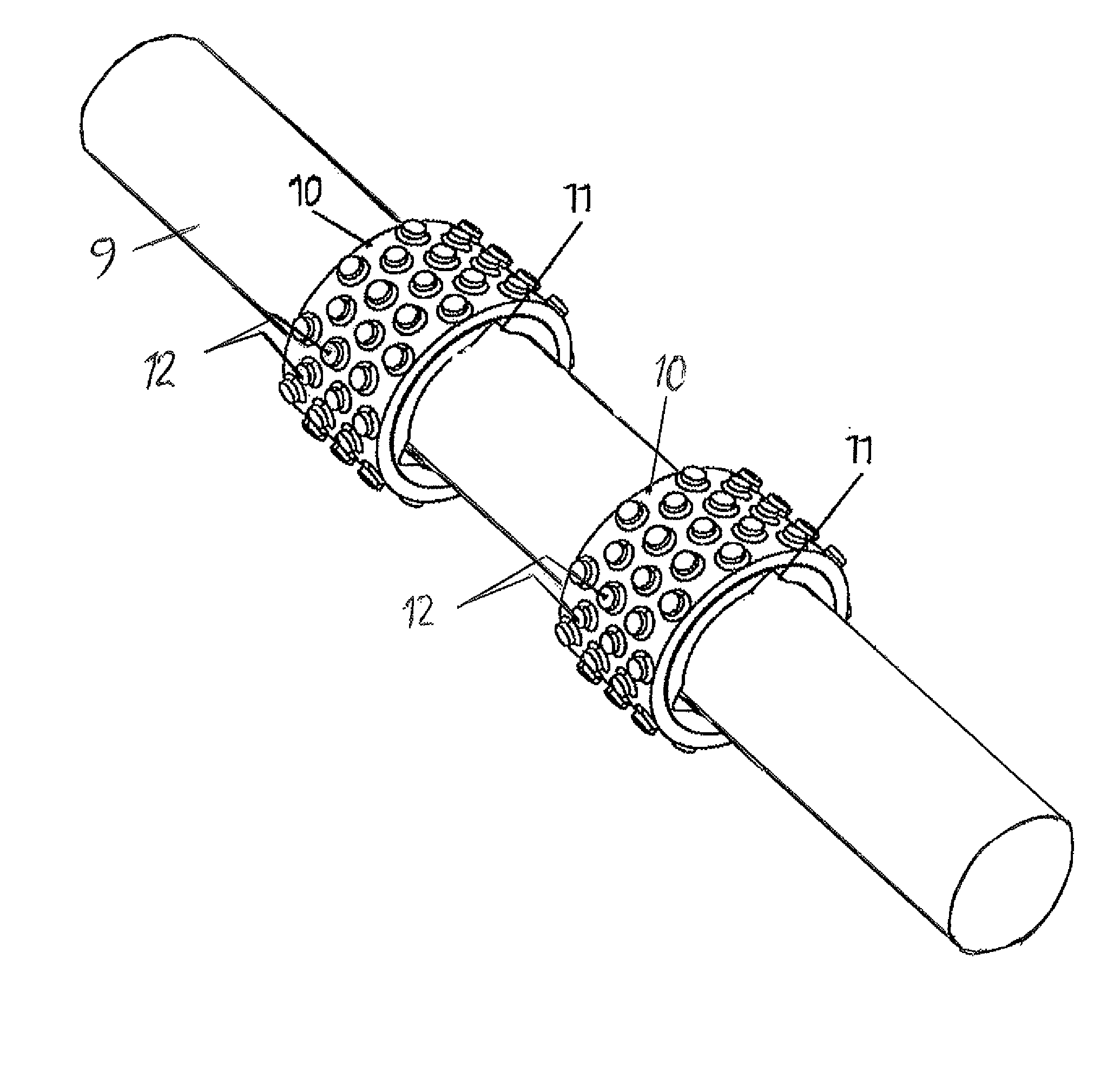
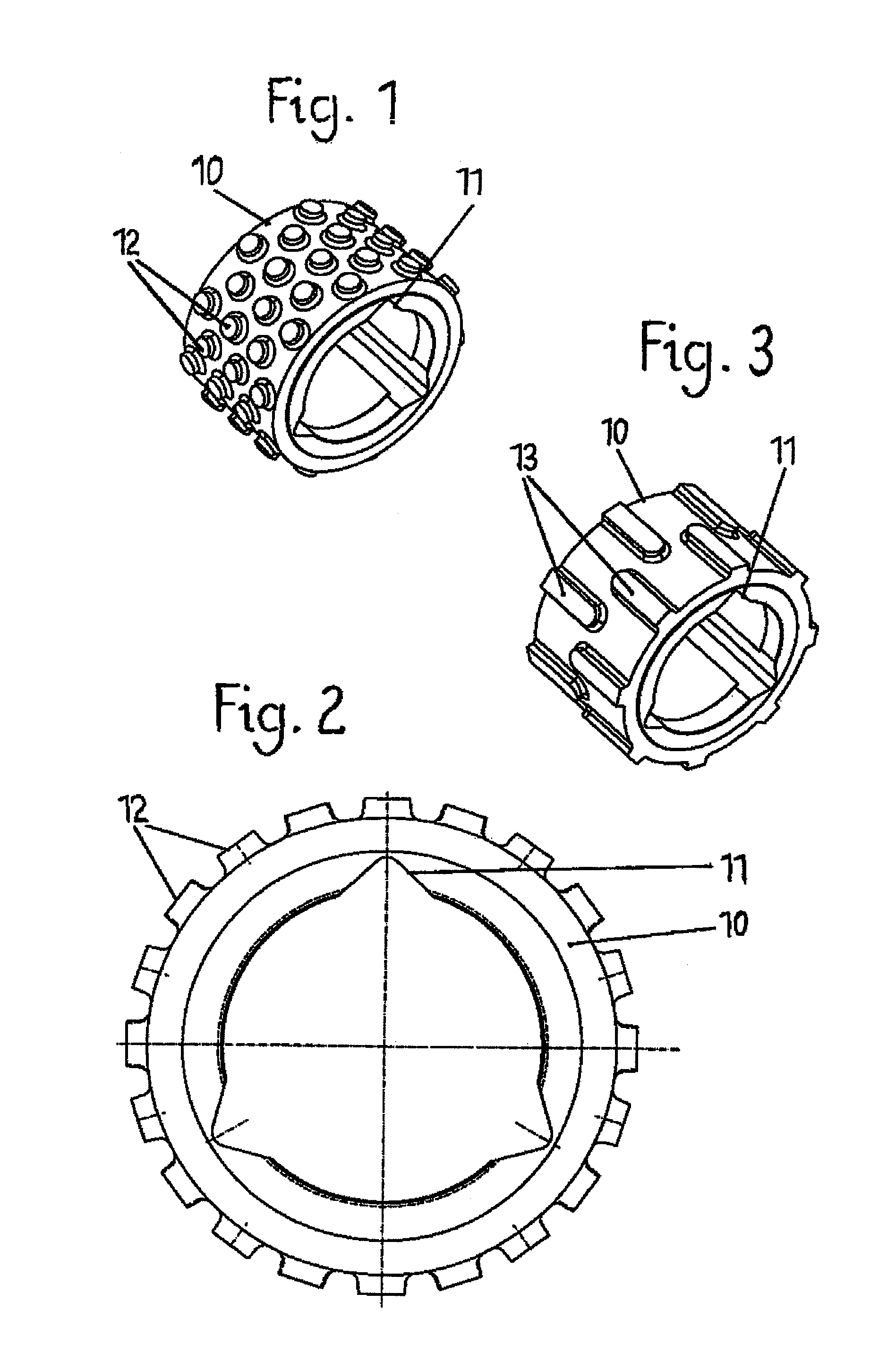
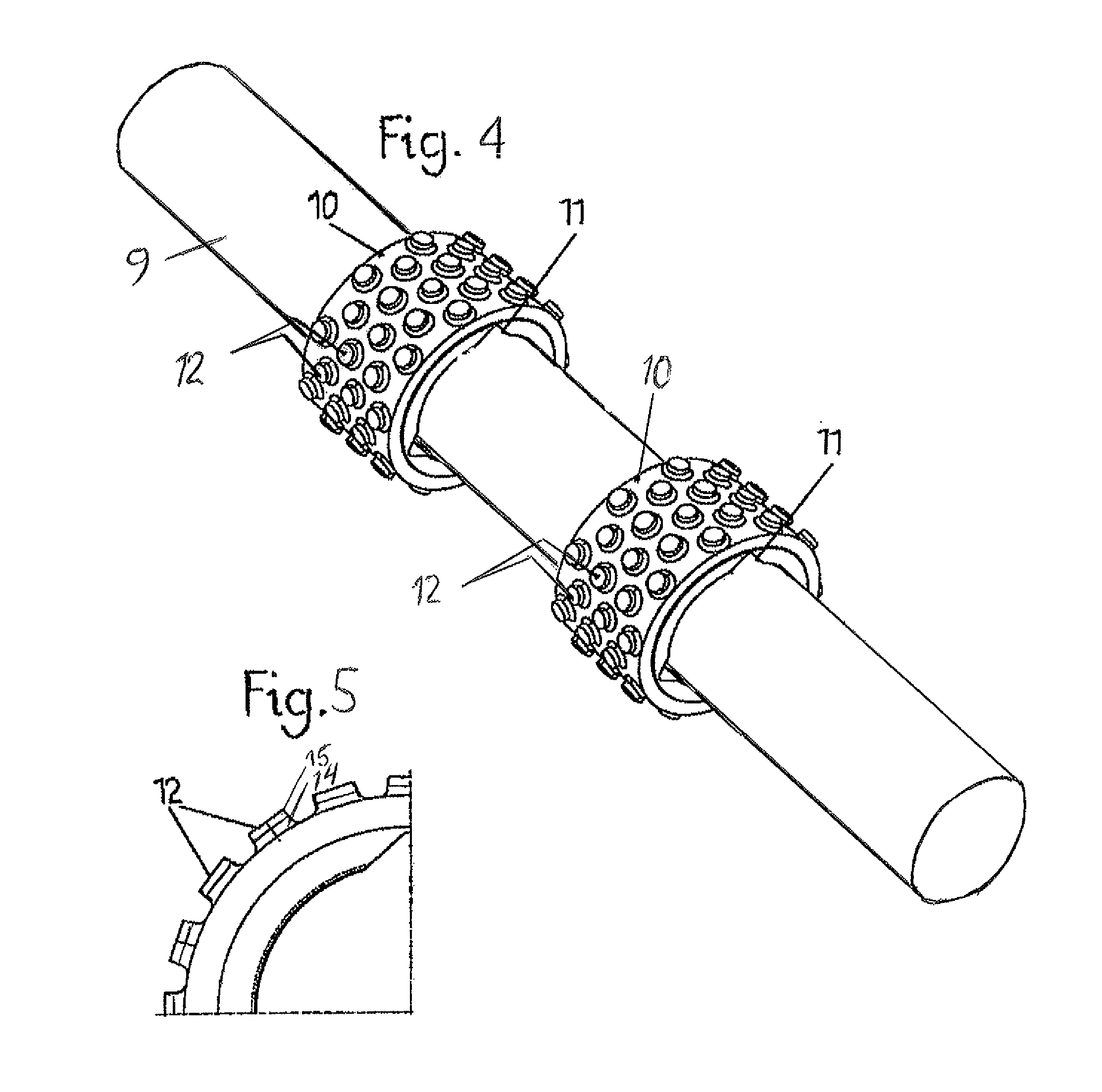
[0014]In the roll crusher according to the invention, which is assigned to a cement clinker cooler, a plurality of crushing rolls, e.g., five or six crushing rolls, are arranged in parallel next to one another, said crushing rolls extending over the entire cooler width transversely to the cooler conveying direction and being driven in their plurality in opposite directions. In this case, the crushing rolls each have a rotatably mounted supporting tube 9, onto which in each case a plurality of crushing rings 10 to be connected to the supporting tube in a rotationally fixed manner can be pushed, the outer surface of which crushing rings has projecting crushing elements 12. That is to say that in each case a multiplicity of crushing rings 10 are pushed in an interchangeable manner onto the supporting tube 9 of each of the crushing rolls arranged in parallel next to one another, of which crushing rings the crushing ring 10 is shown in FIG. 1, which, like the other crushing rings too, is...


PUM


Abstract

The aim of the invention is to provide a roll crusher for a grate cooler for cooling hot bulk material, in particular hot cement clinker, comprising several parallel crusher rolls. Said rolls are driven in opposite directions and comprise respective rotatably mounted axle tube rolls, onto each of which a large number of crusher rings that can be connected to the axle tube can be pushed. According to the invention, the crusher rings are configured in such a way that crusher elements project from the cylindrical outer face of the crusher rings, said elements being uniformly distributed both over the periphery and over the width of the crusher rings.

Description

BACKGROUND OF THE INVENTION[0001]The invention relates to a roll crusher for crushing hot bulk material, such as, for example, cement clinker discharged from a baking kiln, having at least two crushing rolls which are arranged in parallel, are driven in opposite directions and have a rotatably mounted supporting tube, onto which in each case a multiplicity of crushing rings to be connected to the supporting tube in a rotationally fixed manner can be pushed, the outer surfaces of which crushing rings have crushing elements.[0002]In a cement clinker production line, the blazing hot cement clinker burned from calcined raw cement meal in a rotary tubular kiln is ejected from the kiln discharge end onto a cooler, nowadays mostly onto the cooling grate of a grate cooler, is distributed on the latter and is moved by suitable conveying techniques in the longitudinal direction to the cooler discharge end, cooling air at the same time flowing essentially from bottom to top through the cooling...

Claims


Application Information

Patent Timeline
Patent Type & Authority Patents(United States)
IPC IPC(8): B02C15/16B02C23/00
CPCB02C4/305B02C4/08
Inventor SOMMER, ERICHSCHINKE, KARL
Owner KHD HUMBOLDT WEDAG GMBH
Features
  • Generate Ideas
  • Intellectual Property
  • Life Sciences
  • Materials
  • Tech Scout
  • Unparalleled Data Quality
  • Higher Quality Content
  • 60% Fewer Hallucinations
Learn More