Implantable transducer

a transducer and implantable technology, applied in the direction of sleep inducing/ending devices, sensors, diagnostics, etc., can solve the problems of osseointegration and low fastening effect, and achieve the effect of low fastening effect and easy removal

Active Publication Date: 2012-08-14
OSSEOFON AB
View PDF15 Cites 17 Cited by
  • Summary
  • Abstract
  • Description
  • Claims
  • Application Information

AI Technical Summary

Benefits of technology

[0015]The present invention solves the above problems by connecting the implanted transducer to the medial (inner) parts of the temporal bone by directly connecting the housing, which contains the transducer, to the bone for transmission of the vibrations via a surface of the housing. The housing is pressed with a static force against the bone, which is greater than the signal forces. By this non-screw attachment a height of at least 5-6 mm is saved. The solution demands that a seat is made in the temporal bone in the bottom plane to which the transducer's housing is attached. The transducer is thus not attached for vibration transmission with a conventional osseointegrated screw attachment, but by a static force pressing the transducer housing against the bone surface. Over time osseointegration can occur at the housing surface, however, the fastening effect becomes relatively low due to the flat surface design. The implanted transducer can thus be easily removed in the case of an MRI examination, or upgrading or replacement due to failure.
[0016]In a preferred embodiment the transducer housing has an attachment surface, which is located medially and below to the outer surface of the temporal bone and the static force is maintained with a compliant device on the lateral side of the housing, which is attached to the bone's outer surface. The attachment surface of the temporal bone in the bottom plane is first formed to fit the attachment surface of the transducer housing. This surface can be levelled and any cavities can be filled with bone chips from the drilling of the bone when the hole was made or with bone cement. The device which creates the static force can be made of an elastic material such as silicon, which is compressed by e.g. a band / bar or thread material which is fixed to the lateral side of the skull bone. The band / bar or thread material can also function as the elastic element. In a simplified embodiment suture threads can be used. If a band / bar material with screw attachment is used, it can also serve as a mechanical protection against external impact in the area and prevent damage to the transducer or the temporal bone from possible external force. Such a bone anchored band / bar also provides protection against the radiation of vibration energy from the transducer housing, which reduces the risk of feedback.

Problems solved by technology

Over time osseointegration can occur at the housing surface, however, the fastening effect becomes relatively low due to the flat surface design.

Method used


Image

  • Implantable transducer
  • Implantable transducer
  • Implantable transducer

Examples


Embodiment Construction

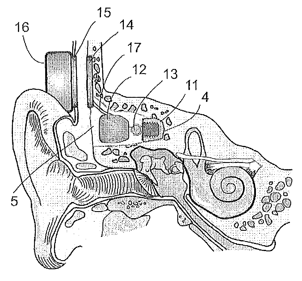
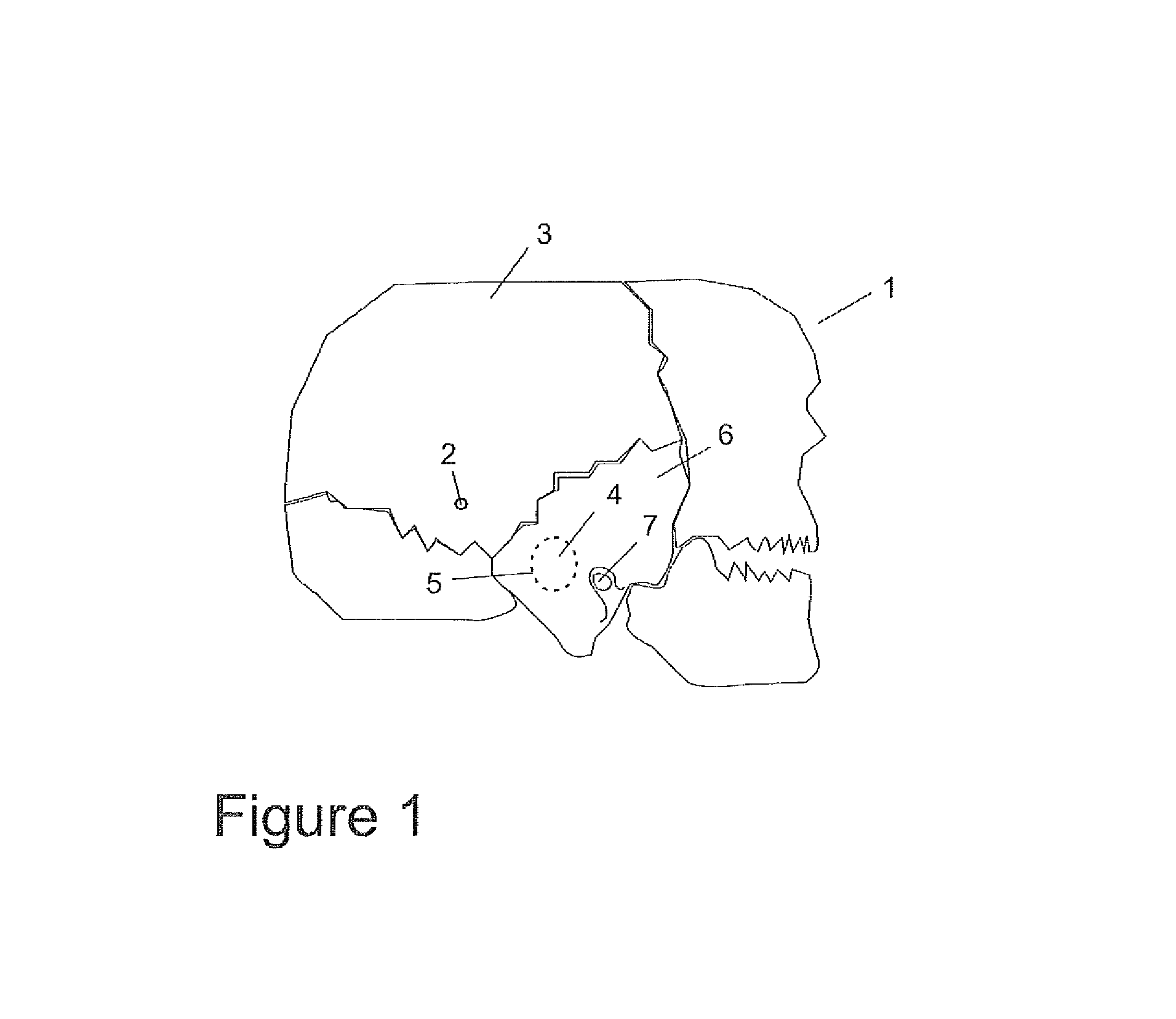
[0048]As is shown in FIG. 1 the skull (1) is composed of different bone plates which are held tightly together with so called sutures. In a conventional bone anchored hearing aid (BAHA) the bone screw (2) is placed in the parietal bone (3). In the present innovation the transducer is connected to the bottom plane (4) of the inner part of a recess (5) in the temporal bone (6). The recess is created directly behind the entrance of the ear canal (7) in that part of the temporal bone which is commonly referred to as the mastoid.

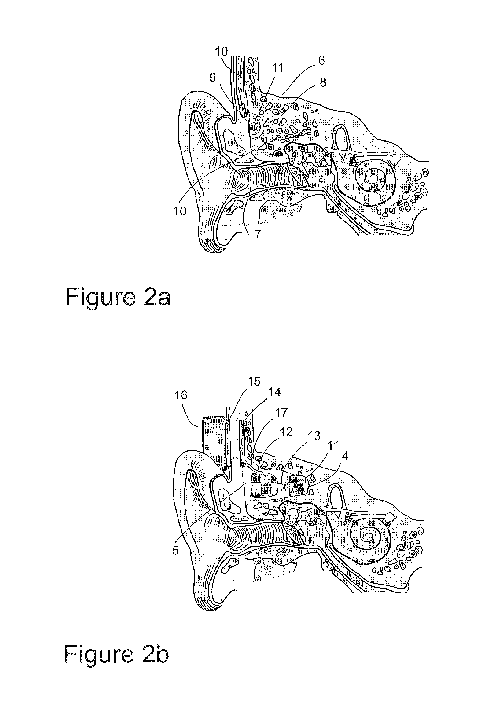
[0049]For medical reasons it is not custom to drill or screw a hole into the bottom plane of the recess (5) where the bone as shown in FIG. 2a consists of many air cells or so called spongy bone (8). Consequently it has been suggested that a bone screw (9) for attachment of an implantable transducer is first installed in the outer layer of compact bone (10) and then the surrounding bone is removed as a bone graft (11). Then a recess is drilled in the bone (5) and...


PUM


Abstract

A method and device for connecting a bone conductor transducer contained in a housing to the skull bone for the transmission of vibrations characterized by, that the housing has at least one surface, which is placed against the bottom plane of a recess shaped in the temporal bone with a static force exceeding the dynamic signal forces.

Description

PRIORITY INFORMATION[0001]The present application claims priority to Swedish Application No. SE0800390-7, filed on Feb. 20, 2008, which is incorporated herein by reference in its entirety.DESCRIPTIONTechnical Area[0002]The following invention concerns a new method and device for connecting an implantable bone conduction transducer to the cranium for effective vibration transmission to the inner ear, which takes minimal space, has a low profile, allows for simple and safe surgical implantation and removal in the case of replacement or temporarily for a MRI examination.Background of the Invention[0003]In hearing aids of the bone conduction type the transducer was until the 1980s, applied against the skin behind the ear with a constant pressure that often was experienced as uncomfortable. The skin also dampened the vibration transmission, which made the sound quality generally poor. In the 1980s bone anchored hearing aids became available where the transducer was connected to a titaniu...

Claims


Application Information

Patent Timeline
Patent Type & Authority Patents(United States)
IPC IPC(8): H04R25/00
CPCH04R25/606H04R2460/13H04R2225/67
Inventor HAKANSSON, BO
Owner OSSEOFON AB
Why Eureka
Try Eureka