
Optical disc label printer, thermosensitive recording printer and thermosensitive recording method

a printing printer and thermosensitive technology, applied in the direction of printing, thermography, instruments, etc., can solve the problems of limited sub-scanning speed, increased power consumption, and increased cost, and achieve the effect of low cost, low cost and high-performan

Inactive Publication Date: 2012-08-14
PANASONIC CORP
View PDF17 Cites 1 Cited by
  • Summary
  • Abstract
  • Description
  • Claims
  • Application Information

AI Technical Summary

Benefits of technology

[0016]An object of the present invention is to provide inexpensive and high-performance optical disc label printer and thermosensitive recording printer by realizing high-speed thermosensitive recording and a recording method with an uncomplicated power control without reducing the power density of a condensed spot.
[0020]According to the present invention, it is possible to realize high-speed thermosensitive recording and a recording method with an uncomplicated power control without reducing the power density of condensed spots. Therefore, it is possible to provide inexpensive and high-performance optical disc label printer and thermosensitive recording printer.

Problems solved by technology

On the other hand, speed in the sub scanning direction is restricted by the feeding pitch of the condensed spots.
Thus, if the speed in the main scanning direction MS is constant and the recording sensitivity of the thermosensitive recording material is constant, the output of the light source such as a semiconductor laser has to be increased in order to make thermal energy per unit time given to the thermosensitive recording material constant, wherefore there are problems such as a power consumption increase and a cost increase.
However, in order to record a gradation image based on a specified image signal while overlapping the condensed spots CS between the pixels, the laser light needs to be modulated in consideration of the overlap of the condensed spots before and after the pixels, thereby presenting a problem of making a control very complicated.Patent Literature 1: Japanese Unexamined Patent Publication No.

Method used


Image

  • Optical disc label printer, thermosensitive recording printer and thermosensitive recording method
  • Optical disc label printer, thermosensitive recording printer and thermosensitive recording method
  • Optical disc label printer, thermosensitive recording printer and thermosensitive recording method

Examples


first embodiment

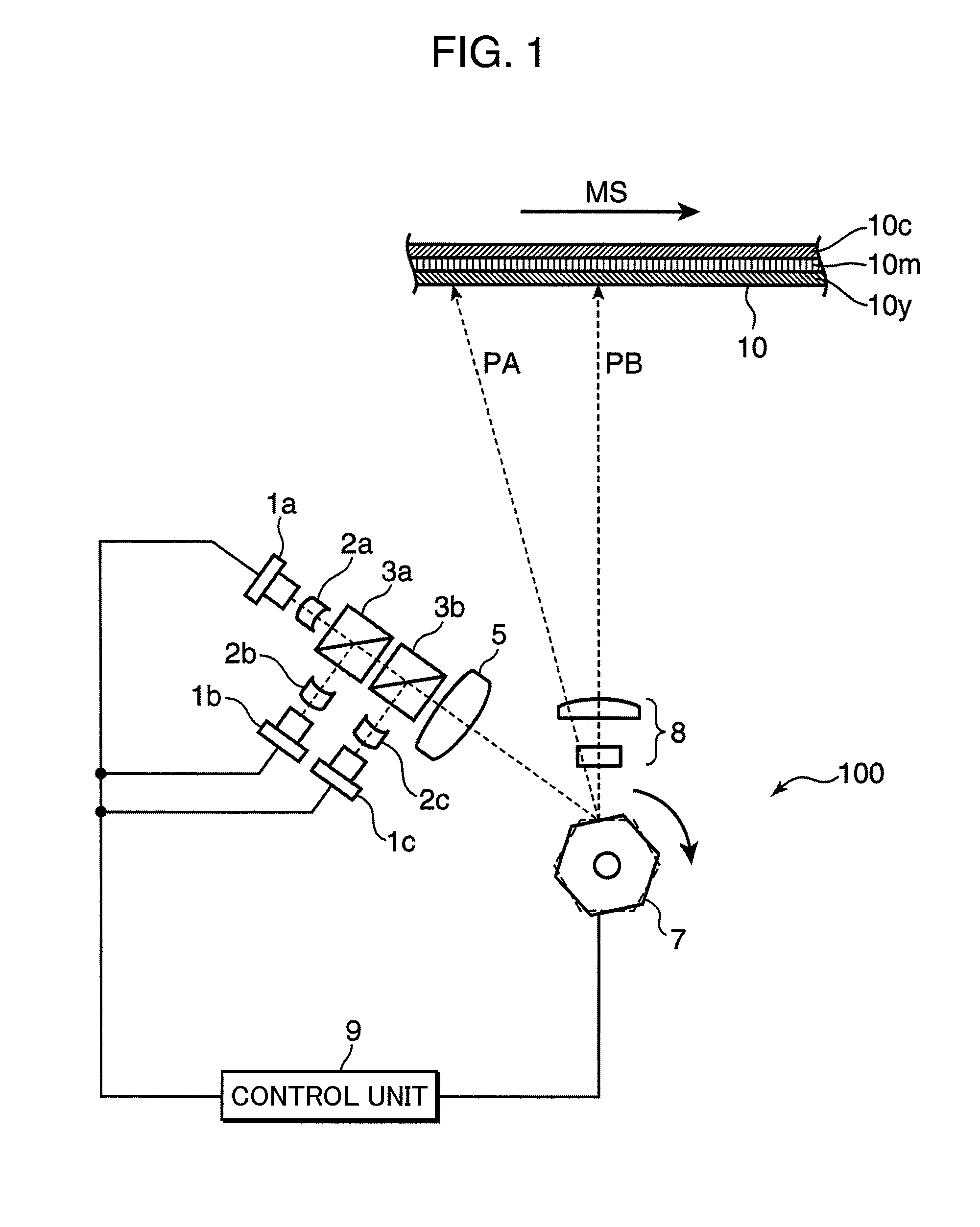
[0040]FIG. 1 is a schematic construction diagram of an optical unit 100 of a thermosensitive recording printer according to a first embodiment of the present invention. The optical unit 100 shown in FIG. 1 is provided with three semiconductor lasers 1a to 1c as laser light sources, three beam shaping lenses 2a to 2c, two dichroic prisms 3a, 3b, a collimator lens 5, a polygon mirror 7, an fθ lens 8 and a control unit 9. By this optical unit 100, light from the light sources is modulated in conformity with an image composed of a plurality of pixels, and the modulated light is scanned and irradiated to a recording medium to record the image on the recording medium 10. Since the construction of a known thermosensitive recording printer can be used as the construction other than the optical unit 100 of the thermosensitive recording printer of this embodiment, such a construction is neither shown nor described.

[0041]The semiconductor lasers 1a to 1c emit beams of laser light having differ...

second embodiment

[0077]FIG. 12 is a schematic construction diagram of an optical disc label printer according to a second embodiment of the present invention. The optical disc label printer shown in FIG. 12 is provided with an optical head 200, a spindle motor 21 and a control unit 22, wherein the optical head 200 includes three semiconductor lasers 11a to 11c as laser light sources, three dichroic beam splitters 13a to 13c, a collimator lens 15, a reflecting mirror 17, an objective lens 18 and a photodetector 19. Various optical elements employed in conventional optical heads for recording or reproducing information using an objective lens may be added or replaced in the optical head 200.

[0078]The optical head 200 of the optical disc label printer of this embodiment can record and / or reproduce information on and / or from an optical disc 20 such as a CD (Compact Disc), a DVD (Digital Versatile Disc) or a Blu-ray disc similar to an optical head of an ordinary optical disc drive device and can be used ...


PUM


Abstract

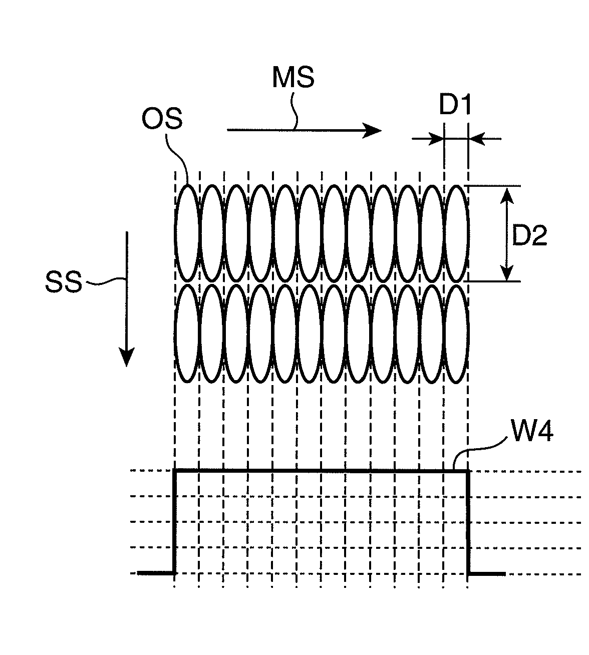
A thermosensitive recording printer is provided with semiconductor lasers 1a to 1c, a polygon mirror 7 for condensing laser light emitted from the semiconductor laser 1a to 1c as condensed spots on a recording medium 10 to perform scanning in a main scanning direction, and a control unit 9 for controlling the output of the laser light. If a ratio of a spot diameter D1 of the condensed spots in the main scanning direction and a spot diameter D2 in a sub scanning direction satisfy a relationship of D1 / D2≦½ at the time of forming an image composed of a plurality of pixels on the recording medium 10 using laser light, high-speed thermosensitive recording and a recording method with an uncomplicated power control are realized without reducing the power density of the condensed spots.

Description

[0001]This is a U.S. national stage application under 35 USC 371 of international application PCT / JP2008 / 001041, filed on Apr. 21, 2008FIELD OF THE INVENTION[0002]The present invention relates to an optical disc label printer, a thermosensitive recording printer and a thermosensitive recording method for thermally recording an image or the like by irradiating a thermosensitive recording material with laser light.BACKGROUND ART[0003]Printers for thermally recording an image or the like by giving thermal energy to a thermosensitive recording material have been developed. Particularly, printers capable of high-speed recording by using laser light as a heat source have been proposed. Further, thermosensitive recording materials including color formers, developers and light-absorbing dyes on a substrate and producing colors at a density corresponding to given thermal energy have been developed as those capable of recording good images with high quality. A printer for recording an image o...

Claims


Application Information

Patent Timeline
Patent Type & Authority Patents(United States)
IPC IPC(8): B41J2/47
CPCB41J2/32B41J2/471B41J2/475B41M5/26B41M2205/04
Inventor YAMASAKI, FUMITOMOANZAI, JOJIKIMURA, NAOHIRONISHIHARA, TAKASHI
Owner PANASONIC CORP
Learn More