Personnel safety utilizing time variable frequencies

a technology of time variable frequency and safety, applied in the direction of safety devices for lifting equipment, lifting devices, visible signalling systems, etc., can solve the problems of unsatisfactory previous attempts to reduce the frequency of workplace injuries caused by moving equipment, unsatisfactory previous attempts to enhance the safety of personnel working around moving equipment, and inability to accurately and consistently send. , the effect of accurate distance rang

Inactive Publication Date: 2012-08-21
PSST MOBILE EQUIP - RICHARD SHERVEY +1
View PDF20 Cites 106 Cited by
  • Summary
  • Abstract
  • Description
  • Claims
  • Application Information

AI Technical Summary

Benefits of technology

[0034]Advantageously the wireless monitoring of the tags by the reader uses a chirp spread spectrum technique so as to provide high noise and multi-path resistance.
[0038]Advantageously the garment antennas are miniaturized planar antennas arranged so that superposition of the radiation patterns of the garment antennas provide 360 degree coverage around the garment, for example in the shape of a torus. Further advantageously the garment antennas ground planes minimize the effect on radiation performance of the garment antennas of a worker's body when the worker is wearing the garment.
[0041]The antennae system provides an approximation of spherical coverage using a multiple antennae array positioned on the body so as to reduce radio interference of other human bodies in close proximity to the user.
[0044]The improved antenna system according to one aspect of the present invention provides the ability to accurately and consistently send and receive signals regardless of the proximity of other users, and thus to provide a means for indentifying the identity and location of every individual user even in a crowd of users.
[0045]The present invention may provide the following useful advantages: Accurate distance ranging, reliable operation in very harsh, and highly reflective radio environments, be capable of high speed ranging, which make the system suitable for mounting on moving objects, platforms or mobile equipment, or machines. Very robust signal, minimizes holes, and resists fading in high, radio wave saturated areas. The system can detect person from virtually every aspect: front, back, sideways, prone. The system has a limited capacity to “see around corners” even in highly reflective venues, and it this not strictly a line of sight system so that “line-of-sight” as used herein is intended to include limited seeing around corners. The system has the ability to identify persons and objects, and to differentiate between them even when groups of people are present, and is resistant to human body interference. The presence of the machine operator may be detected using an operator-present sensor feature when he / she is at the controls of the machine, our system will then ignore the operator until such time as he / she leave the operating compartment of the machine, once the operator leaves the cab or control area, our system will respond to the tag once more. Machines may be outfitted with machine object tags, in order for machines to recognize each other in areas where multiple machines are in use, especially when operating machines with limited fields of view. The operator-present feature may be adapted to implement safe walking areas within the confines of work place buildings. That is, operator-present object tags may be mounted to railings, or otherwise positioned to create an area in which the system will ignore the presence of body tags worn by the workers, unless within an inner reaction or danger zone where collision is imminent, in which case machine motion is altered, for example automatically stopped.

Problems solved by technology

It is well known that larger equipment moving at faster speeds poses a greater risk to other personnel working in the same vicinity.
Previous attempts to reduce the frequency of workplace injury from moving equipment have not been satisfactory.
As set out above, previous attempts to use RFID tags to enhance the safety of personnel working around moving equipment have proved unsatisfactory.
Previous systems employing RFID tags have not been sufficiently tied in to the operating system of the piece of equipment and therefore have only provided an audible warning to the operator of the equipment or the individual wearing the RFID tag when the worker gets too close to the equipment.
Due to the loud noise levels at many such worksites, these types of audible signals may be insufficient to adequately ensure that the piece of equipment does not continue to strike the worker.
In addition, there has been resistance to implementing immobilization of such equipment in response to proximity of RFID tags due to the adverse impact that such immobilization will have on the productivity of the job site.
In particular, stopping the movement of a machine results in at least a portion of time during which the machine is not performing its intended function and therefore the overall efficiency of the industrial process is reduced.
An additional difficulty with prior uses of RFID tags for safety devices has been the location of only a single RFID tag at a point source locatable on the user.
Such a point source RFID tag may be susceptible to being screened or blocked from being read by an antenna on a vehicle depending on the orientation of the body of the worker wearing such a tag and therefore may potentially result in a false negative reading for the presence of an RFID tag.
Such a false negative reading may in turn lead to the piece of equipment striking and injuring the worker.

Method used


Image

  • Personnel safety utilizing time variable frequencies
  • Personnel safety utilizing time variable frequencies
  • Personnel safety utilizing time variable frequencies

Examples


Embodiment Construction

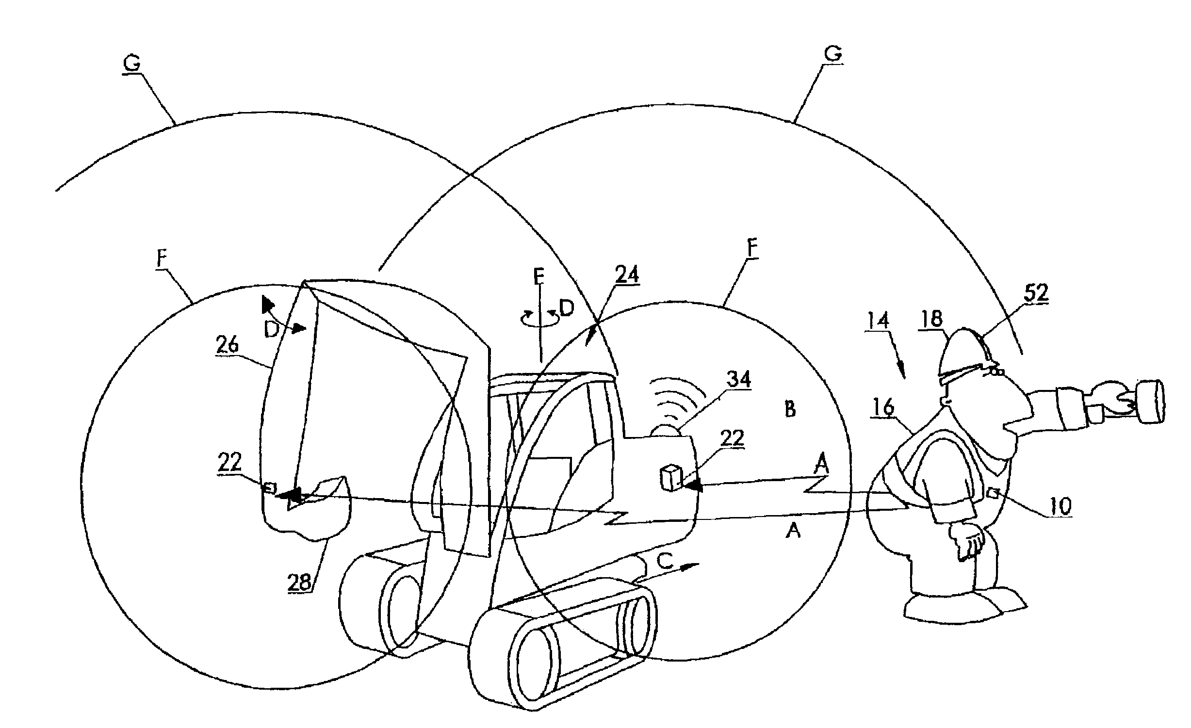
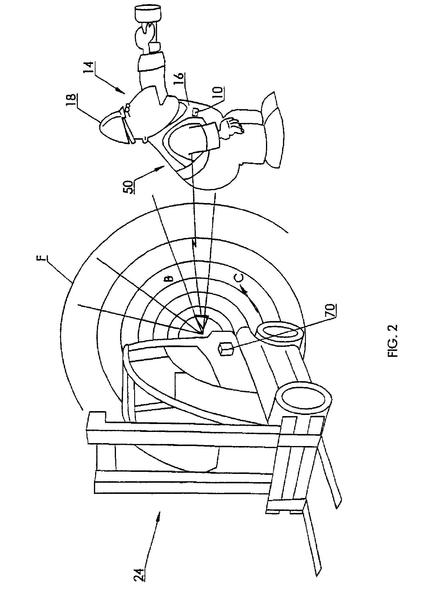
[0079]As seen in the accompanying Figures, wherein similar characters of reference denote corresponding parts in each view, the RFID based personnel safety system according to one aspect of the present invention includes an RFID tag 10 which contains a transponder 10a. The tag may for example be worn by a workman 14 either on an item of clothing 16, or on a hardhat 18 or the like.

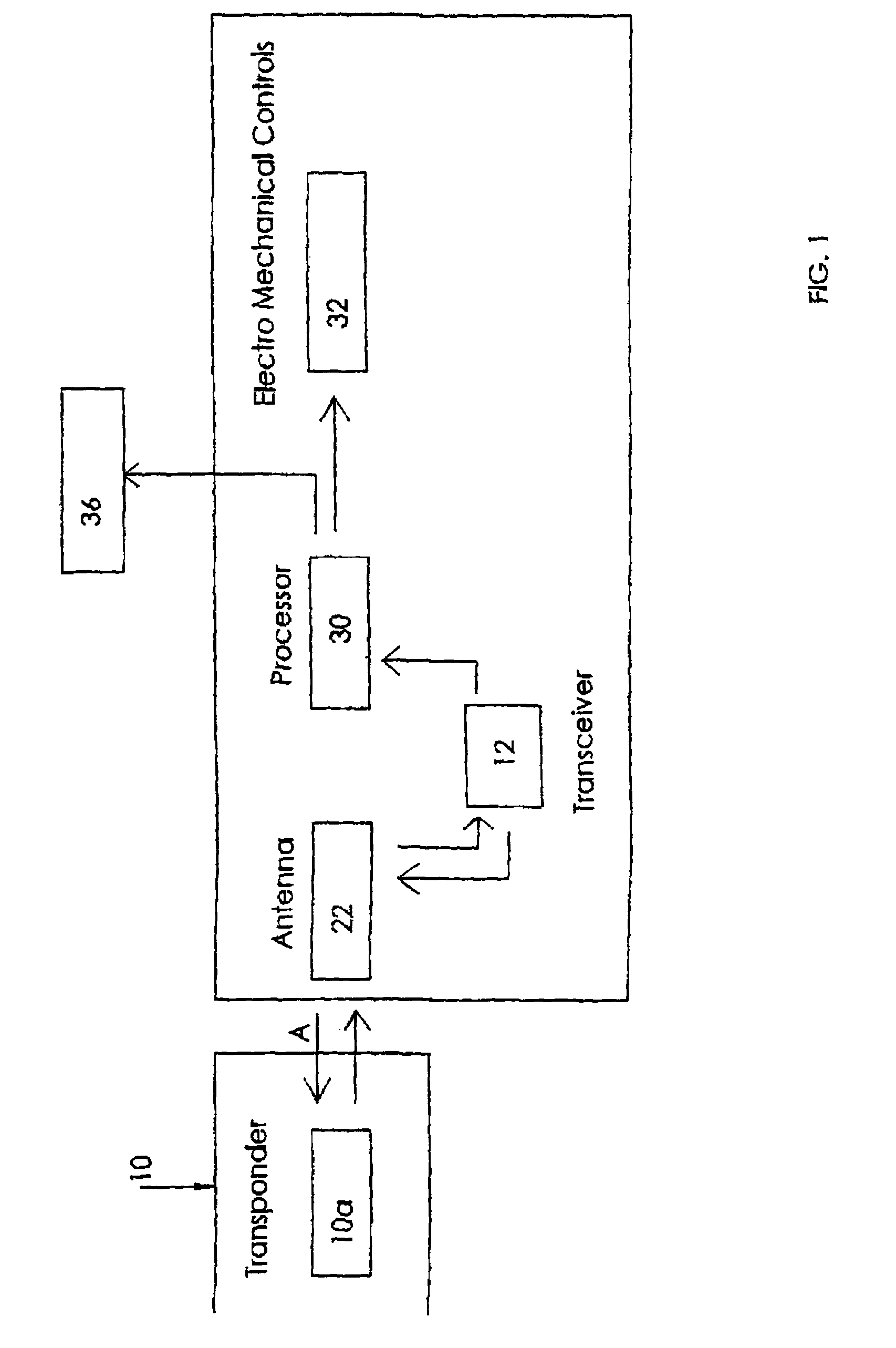
[0080]Transponder 10a within tag 10 is in discontinuous radio frequency communication such as indicated by arrow line A with a transponder detection system 20. Transponder detection system 20 includes at least one antenna 22, which, in a preferred embodiment, may be one or more directional antennas, cooperating with transceiver 12.

[0081]In the case of use of a single antenna, it can be an omnidirectional antenna, unidirectional antenna, or, preferably, a directional antenna, such as for example a dipole antenna or yagi antenna taught in the prior art, for increased directionality and range.

[0082]Multiple an...


PUM


Abstract

A system to improve safety of workers who are in proximity to mobile machines includes a machine mountable radio-frequency identification reader that wirelessly monitors radio-frequency identification tags worn by workers moving relative to and in proximity to a mobile machine when the reader is mounted on the machine. The reader includes a processor and an antenna front-end which is switchable between an omni-directional antenna or at least one directional antenna. The omni-directional antenna is mountable so as to monitor a machine circumference completely around the mobile machine. Each directional antenna is mountable so as to monitor only either a front or a back of the mobile machine relative to the machine's direction of motion.

Description

FIELD OF THE INVENTION[0001]This invention relates to the field of devices insuring personnel safety, and in particular to a method and apparatus employing radio frequency identification based proximity sensing, warning and machine shut-down for collision avoidance between personnel and articulated or mobile industrial machinery.BACKGROUND OF THE INVENTION[0002]Workplace safety is of great importance. As the demands for efficiency in ensuring competitiveness of industries increases, so too does the size of the equipment as well as the speed at which these pieces of equipment move. It is well known that larger equipment moving at faster speeds poses a greater risk to other personnel working in the same vicinity.[0003]Applicants are aware of statistics such as contained in a report entitled “Claims Statistics for Accidents Involving Selected Mobile Equipment” for all industries in British Columbia, Canada which indicates that for the period 2001-2005 the collective number of short ter...

Claims


Application Information

Patent Timeline
Patent Type & Authority Patents(United States)
IPC IPC(8): G08B21/00B60W30/08B60W30/09
CPCF16P3/147G01V15/00G07C9/00111G07C9/00007G07C2009/0092B66F17/003G07C9/20G07C9/28
Inventor SHERVEY, RICHARD CLAYTONDASILVA, JOHNCHAMSEDDINE, AHMADHAUBRICH, PETER
Owner PSST MOBILE EQUIP - RICHARD SHERVEY
Why Eureka
Try Eureka