
Communication device, communication system, communication method, and program

a communication device and communication system technology, applied in the field of communication technology, can solve the problems of frame transfer failure, frame transfer failure, transfer performance degradation, etc., and achieve the effect of reducing the number of frames and frame transfers, improving the transfer efficiency, and improving the transfer efficiency

Inactive Publication Date: 2012-08-21
NEC CORP
View PDF14 Cites 31 Cited by
  • Summary
  • Abstract
  • Description
  • Claims
  • Application Information

AI Technical Summary

Benefits of technology

The patent text describes a problem in network communication where the transfer of frames between devices can be slow and congested. This is due to the need for the frame to flow through multiple components in the software and hardware, which can lead to a decrease in processing speed. The invention aims to provide a solution that allows for a high-speed transfer of frames while suppressing costs. The solution involves mounting a terminating means to terminate a session of a TCP between devices and establishing a TCP session to make communication. The termination means receives a TCP packet and transmits a response packet to the transmission side, as well as a unique connection request to the reception side. The invention also includes methods for acquiring and preserving an encryption key, and encrypting and decrypting data using the preserved encryption key. The technical effects of the invention include improved processing speed and reduced costs for network communication.

Problems solved by technology

And, hardware-executing the above-mentioned process as it stands in a simplified way necessitates a large-scale scheme such as a TCP Offload Engine (TOE), which gives rise to the problem as well with an increase in both of a circuit scale and a cost.
In addition hereto, in the prior art 1, not only the encapsulation but also the encryption / decoding process in the SSL are software-executed in the CPU, and this point also gives rise to the problem that the frame cannot be transferred at a high speed.
And, it is known that the problem that the transfer performance deteriorates and the frame cannot be transferred at a high speed occurs because a congestion control of the TCP result being duplicated in the TCP over TCP (non-patent document 3).

Method used


Image

  • Communication device, communication system, communication method, and program
  • Communication device, communication system, communication method, and program
  • Communication device, communication system, communication method, and program

Examples


first embodiment

[0161][First Embodiment]

[0162]In the first embodiment of the present invention, as shown in FIG. 33, in establishing the SSL session, a TCP session is established between a TCP of a CPU 100 within a session relay device 10 and a TCP of the intermediate driver, and a TCP session is further established between a TCP of the gateway device 20 and a TCP of the intermediate driver so as to prevent the congestion control in the TCP from being taken between the session relay device 10 and the gateway device 20. Likewise, a TCP session is established between a TCP of the CPU 100 within the session relay device 10 and a TCP of the intermediate driver, and a TCP session is further established between a TCP of a CPU 200 within the gateway device 30 and a TCP of the intermediate driver so as to prevent the congestion control in the TCP from being taken between the session relay device 10 and the gateway device 20. Further, likewise, a TCP session is established between a TCP of a CPU within the ...

second embodiment

[0448][Second Embodiment]

[0449]The second embodiment of the present invention differs from the first embodiment in a point of connecting the intranet 2 and the intranet 3 not through the Internet 1 but directly, and further, establishing the SSL session (secure TCP session) between the gateway device 20 and the gateway device 30 not through the session relay device 10 but directly.

[0450]A configuration and an operation of the terminal 21, the server 31, the HUB 22, the HUB 32, the gateway device 20, the gateway device 30, the intranet 2, and the intranet 3 in the second embodiment are identical that of the first embodiment except for an operation of setting up the session from the gateway device 30 toward the gateway device 20, or the session from the gateway device 30 toward the gateway device 20.

[0451]In the second embodiment, not only a closed LAN but also an open WAN such as Internet may be employed for the intranet 2.

[0452][Explanation of a Configuration]

[0453]FIG. 17 is a bloc...

third embodiment

[0562][Third Embodiment]

[0563]The third embodiment of the present invention differs from the second embodiment in a point that the processing speed acceleration engine 3014 does not exist within the gateway device 30, and a gateway application 3001A exists instead of the processing speed acceleration engine control 3001.

[0564]A configuration and an operation of the terminal 21, the server 31, the HUB 22, the HUB 32, the gateway device 20, the intranet 2, and the intranet 3 in the third embodiment are identical to that of the second embodiment.

[0565]In the third embodiment, not only a closed LAN but also an open WAN such as Internet may be employed for the intranet 2.

[0566][Explanation of a Configuration]

[0567]FIG. 19 is a block diagram having a configuration of each apparatus and a transfer path of the frame in the third embodiment shown in details.

[0568]The gateway device 30 differs from the gateway device 30 in the second embodiment in a point that the processing speed acceleratio...


PUM


Abstract

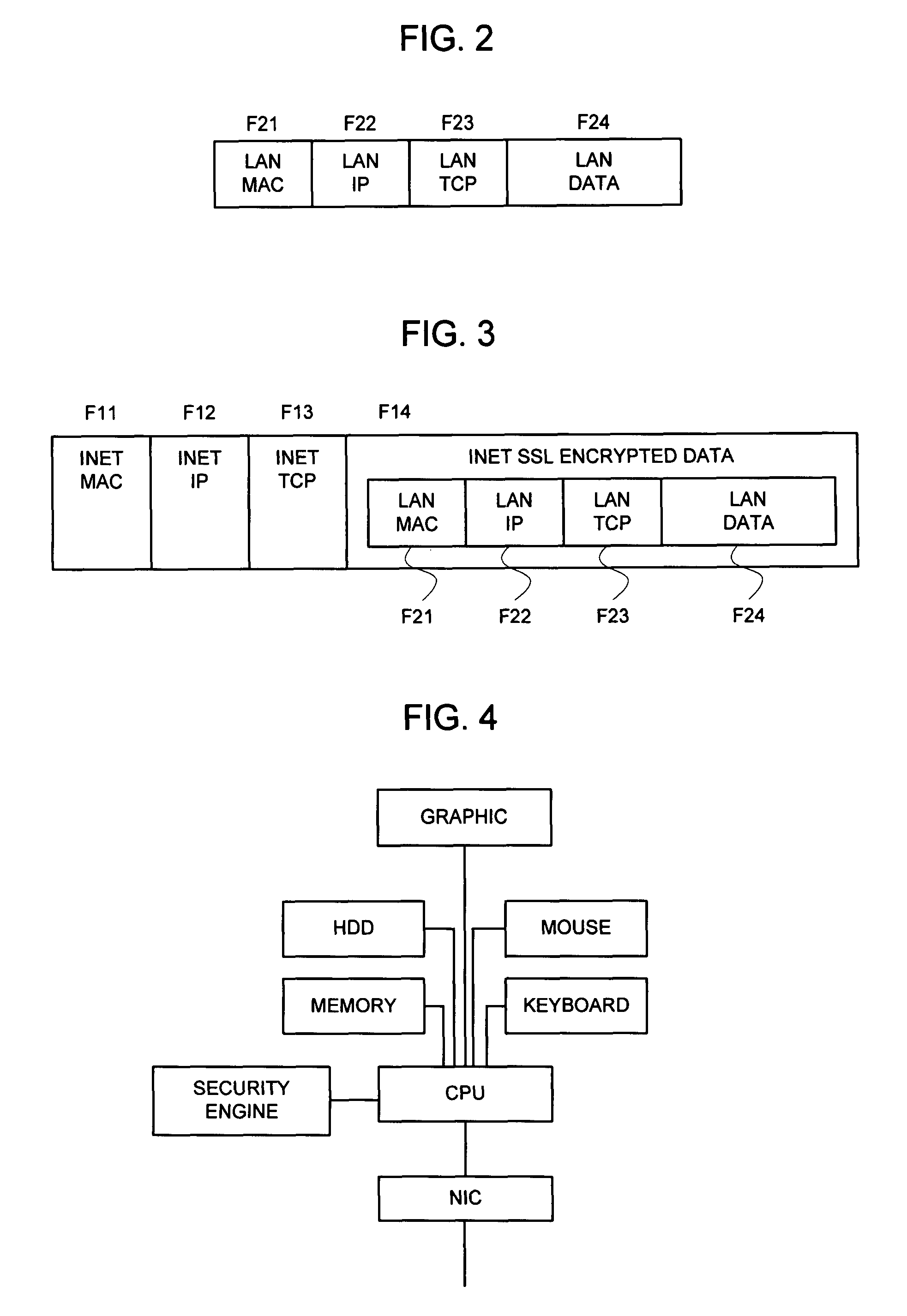
A TCP 2003 is terminated in an intermediate driver 2006 within a gateway device 20, a TCP 3003 is terminated in an intermediate driver 3006 within a gateway device 30, and a frame is transferred between the intermediate drivers with a method not causing a congestion control such as a UDP. Besides, an SSL session is constructed between an SSL 2002 and an SSL 3002, and upon completing construction of the session, a public key and a secret key are sent by means of an Ethernet frame from a processing speed acceleration engine control to a processing speed acceleration engine. Thus, the gateway device transfers the frame not through a CPU but by employing the processing speed acceleration engine within an NIC in later communication between a terminal 21 and a server 31.

Description

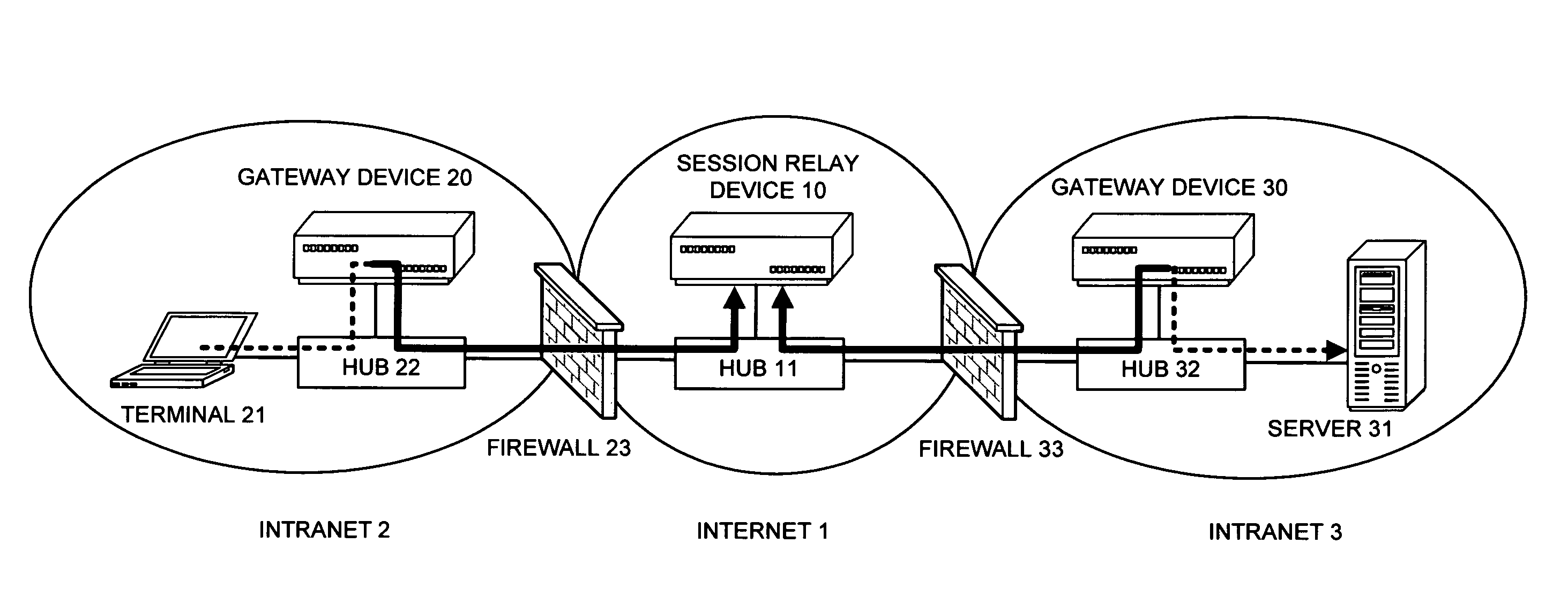
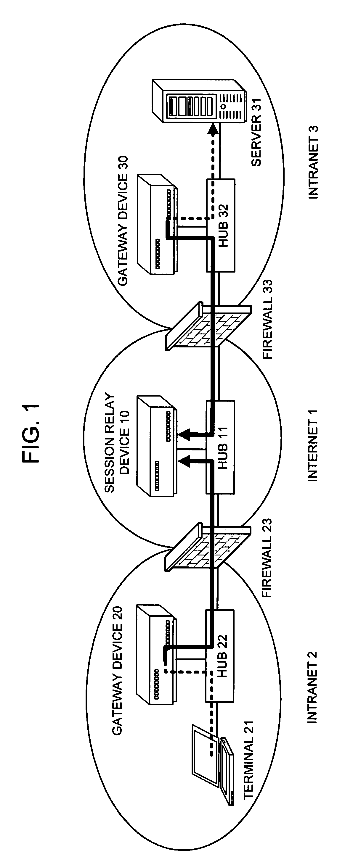
APPLICABLE FIELD IN THE INDUSTRY[0001]The present invention relates to a communication technology, and more particularly to a or enhancing a transfer speed of data, and accommodating data at a large scale in Ether-over-SSL communication.BACKGROUND ART[0002]At first, a prior art 1 will be explained. Conventionally, the technology has been proposed for mutually connecting a plurality of intranets mutually connected via Internet etc. by the Ether-over-SSL communication so that they can be utilized as an identical LAN segment (Non-patent document 1).[0003]FIG. 1 is a block diagram illustrating a configuration of a network in such a prior art.[0004]An Internet 1, which is configured of a session relay device 10, a Firewall 23, and a Firewall 33, or other appliances, is a wide area network (WAN) for making communication between each of these apparatuses and the other. In FIG. 1, each of the apparatuses within the Internet 1 is mutually connected to the other via a HUB 11, and is also conn...

Claims


Application Information

Patent Timeline
Patent Type & Authority Patents(United States)
IPC IPC(8): G06F9/00H04L9/08H04L12/66H04L12/70H04L29/08
CPCH04L63/0428H04L63/166H04L69/16H04L69/161H04L69/163
Inventor ENOMOTO, NOBUYUKIYOSHIMI, HIDEOHIDAKA, YOUICHI
Owner NEC CORP
Learn More