
Device for the controlled power consumption of electric drives in machinery and machine including the device for processing printing material

a technology of electric drives and machines, applied in the direction of motors/generators/converter stoppers, dynamo-electric converter control, instruments, etc., can solve the problem of power consumption that is still lower than the acceptable peak load limit than the initial demand taken from the power system

Inactive Publication Date: 2012-08-28
HEIDELBERGER DRUCKMASCHINEN AG
View PDF33 Cites 3 Cited by
  • Summary
  • Abstract
  • Description
  • Claims
  • Application Information

AI Technical Summary

Benefits of technology

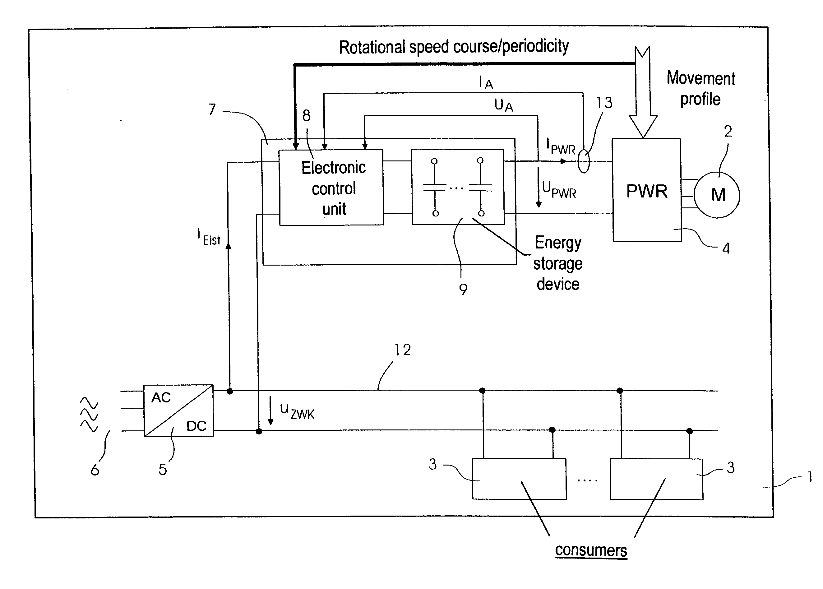
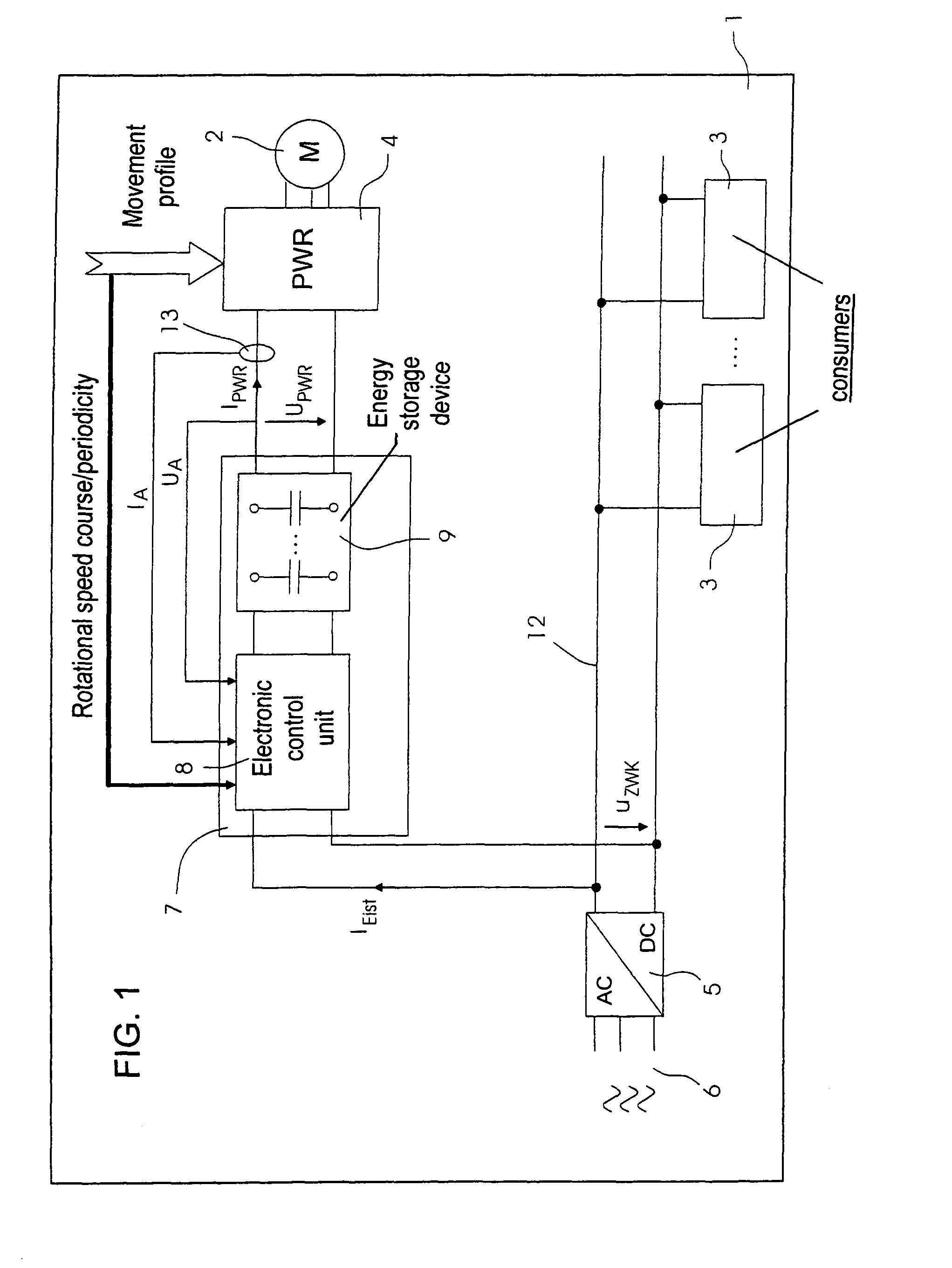
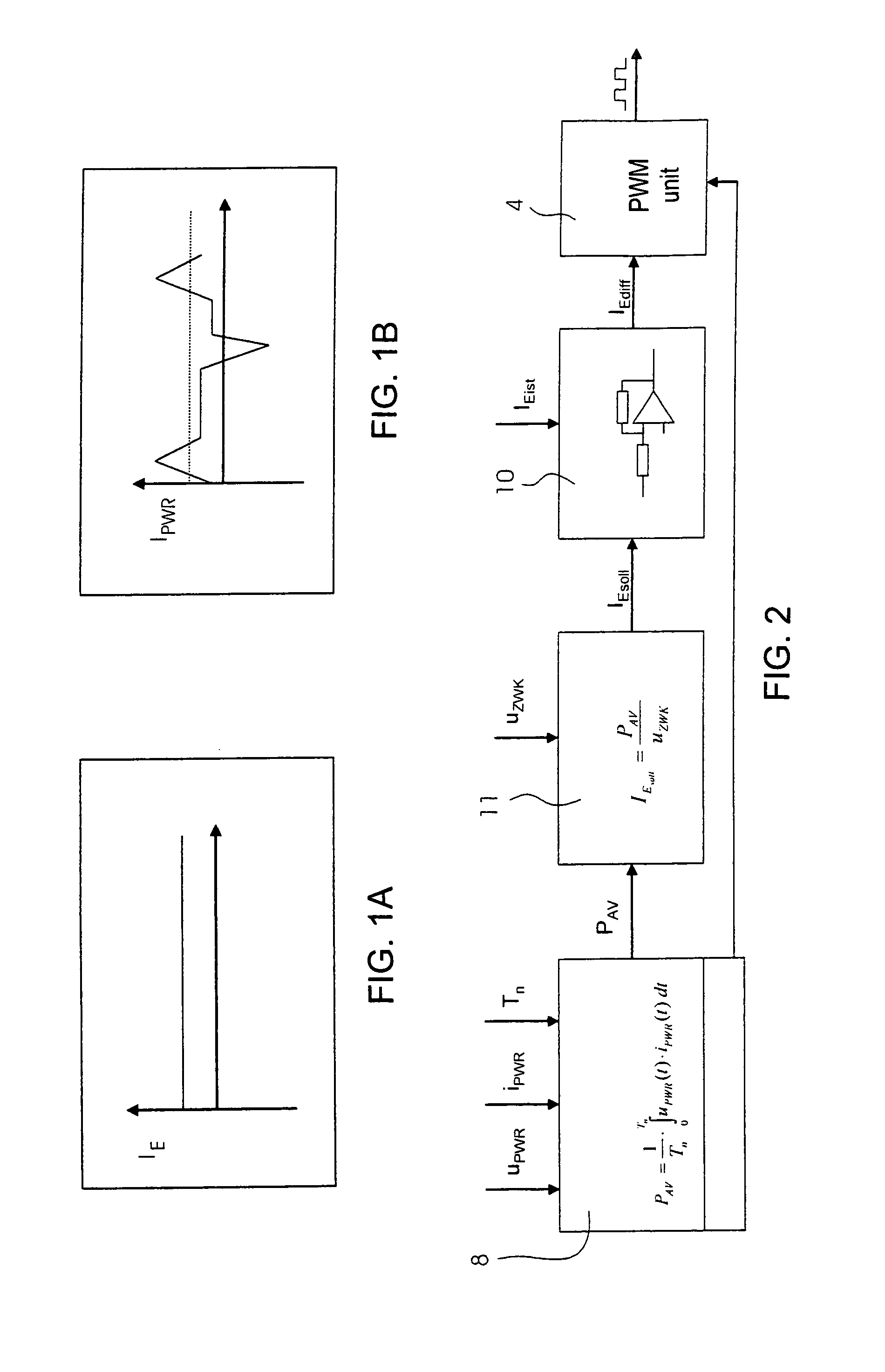
The invention is a device for controlling the power consumption of electric drives in machinery. The device calculates in advance the electric power required by the electric drive based on the motion profiles of the electric drive. This allows for a more efficient use of power in the machinery, as the device can be designed to accommodate the average power demand of the electric drives, rather than the peak load demand. The device includes a power electronics system that can calculate the energy demand of all electric drives in a machine, and an energy storage device to absorb peak loads. The use of an inverter and an energy storage device helps to keep the power supply system of the machine as low as possible.

Problems solved by technology

However, the amount of power higher than the initial demand that is taken from the power system is still lower than the acceptable peak load limit.

Method used


Image

  • Device for the controlled power consumption of electric drives in machinery and machine including the device for processing printing material
  • Device for the controlled power consumption of electric drives in machinery and machine including the device for processing printing material
  • Device for the controlled power consumption of electric drives in machinery and machine including the device for processing printing material

Examples


Embodiment Construction

[0025]Referring now to the figures of the drawing in detail and first, particularly, to FIG. 1 thereof, there is seen a printing press 1 with a number of power consumers 3, one of which is illustrated in greater detail as an electric motor 2. The further direct current consumers 3 may also be electric motors. The direct current consumers 3 and the electric motor 2 are connected to a direct current voltage link circuit or DC circuit 12 of the printing press 1. This direct current voltage link circuit 12 is the highest power supply level of the printing press 1. A rectifier 5 connects the printing press 1 to a 400-Volt three-phase power supply system 6. The rectifier 5 ensures that a link circuit voltage uZWK in the direct current voltage link circuit 12 remains as constant as possible. The electric motor 2 in FIG. 1 is electronically controlled and supplied with power through an inverter 4 for four-quadrant operation. The inverter 4 allows continuous adjustment of the rotational spee...


PUM


Abstract

A device for controlling electric drives in machinery includes an electronic control unit for calculating in advance the electric power required by the at least one electric drive as a function of motion profiles of the electric drive. A printing material processing machine having the drive, is also provided.

Description

CROSS-REFERENCE TO RELATED APPLICATION[0001]This application claims the priority, under 35 U.S.C. §119, of German Patent Application DE 10 2006 031 796.3, filed Jul. 10, 2006; the prior application is herewith incorporated by reference in its entirety.BACKGROUND OF THE INVENTIONField of the Invention[0002]The present invention relates to a device for controlling electric drives in machinery. The invention also relates to a machine, including the device, for processing printing material.[0003]Production machinery with high-performance electric drives in the region of 100 KW and higher put a non-negligible strain on the alternating current supply system of the power supply industry. In particular, machinery having a load which fluctuates to a high degree put a lot of strain on the power supply system. The resultant peak loads must be compensated for by the power supply in an appropriate way, i.e. the power supply of the machine must be constructed to ensure the power supply even in th...

Claims


Application Information

Patent Timeline
Patent Type & Authority Patents(United States)
IPC IPC(8): H02P27/06
CPCH02J1/14
Inventor KLEIBAUMHUTER, KLAUS-DIETERKUNZ, JURGENMEYER, HELMUTREITER, JOSEFSCHULZ, ANDREAS
Owner HEIDELBERGER DRUCKMASCHINEN AG
Learn More