Radiant heating and cooling panel

a technology of heating and cooling panel and radiator, which is applied in the direction of air heater, heating type, lighting and heating apparatus, etc., can solve the problems of increasing labor and costs, affecting the widespread adoption of consumers, and uneven heating/cooling and noise, so as to improve mechanical contact, promote efficient heat transfer, and increase sound isolation

Inactive Publication Date: 2012-09-04
TALBOTT SOLAR & RADIANT HOMES
View PDF43 Cites 4 Cited by
  • Summary
  • Abstract
  • Description
  • Claims
  • Application Information

AI Technical Summary

Benefits of technology

[0032]Applicant thus discloses a novel heat transfer plate that provides numerous benefits over conventional heat transfer plates. The heat transfer plate comprises a groove providing an offset channel for a hydronic radiant tube within the panel that obviates the need to thread the hydronic tubes through the joists in a ceiling installation or the studs in a wall installation. In an alternative embodiment, specific emissivity coatings on each side of the radiant panel further promote the efficient transfer of heat. The Applicant's system provides increased sound isolation and is robust enough to withstand the crushing forces associated with a floor installation. In a concealed installation, applicant's disclosed plates are in better mechanical contact with the drywall than conventional concealed installations.

Problems solved by technology

Uneven heating / cooling and noise have traditionally been problems in a traditional air convection heating and cooling system.
Despite the many benefits of radiant heating and cooling systems, there are still problems hindering their widespread adoption by consumers.
One drawback involves the placement of the hydronic tubes used to deliver heat energy to and pull heat energy from the room being temperature regulated.
Problems in the past faced by installers of hydronic radiant heating and cooling systems, and homeowners using such systems are related to the shape of the heat transfer plates typically nailed or screwed to ceiling joists, or to studs in a wall.
This occurs numerous times in each room in which the system is installed, increasing labor and costs.
Additionally, this installation often requires the hydronic tubes to be bent away from the heat transfer plate and around the joists or studs, or away from the heat transfer plate and through the holes drilled in the joists or studs.
This can put tension on the radiant panels and can cause the edges to warp up and away from contact with the drywall.
A problem related to heating and cooling systems in general relates to energy use.
Energy losses occur in the system through less than perfect conduction transfer between the hydronic tube and the radiant panel, through mechanical losses by the pumping process, and through radiant and conductive losses through the supply and return piping itself.
In a ceiling installation, relatively large amounts of energy are lost as a result of intermittent contact between the heat transfer plate and the drywall.
This inefficient heat transfer process works well when there is very good insulation under the entire assembly, as the heat generated migrates into the floor and warms the house, instead of out to the subfloor space.
A second main source of inefficiency relates to the emissivity and conductance on each side of the heat transfer plate.
Heat transferred to the backside of the panel (away from the living space) is generally an inefficient use of energy.
An additional problem occurs in floor installations.
For instance, furniture may be placed on top of the panel after installation, and it is very likely foot traffic will occur over the installation.
These crushing forces can damage the panels, the tubes or both.
However, a similar solution (lowering the temperature of the circulating fluid to offset the expected heat loss) is not feasible in radiant cooling systems, because once the temperature of the liquid is decreased by too much, condensation can occur, damaging the building or home in which the system is installed.

Method used


Image

  • Radiant heating and cooling panel
  • Radiant heating and cooling panel
  • Radiant heating and cooling panel

Examples


Embodiment Construction

[0033]For the following detailed description and claims, the term “living space” shall refer to the area in a home or building in which the occupants are commonly found.

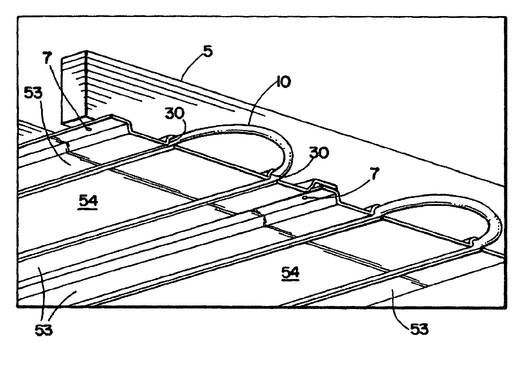
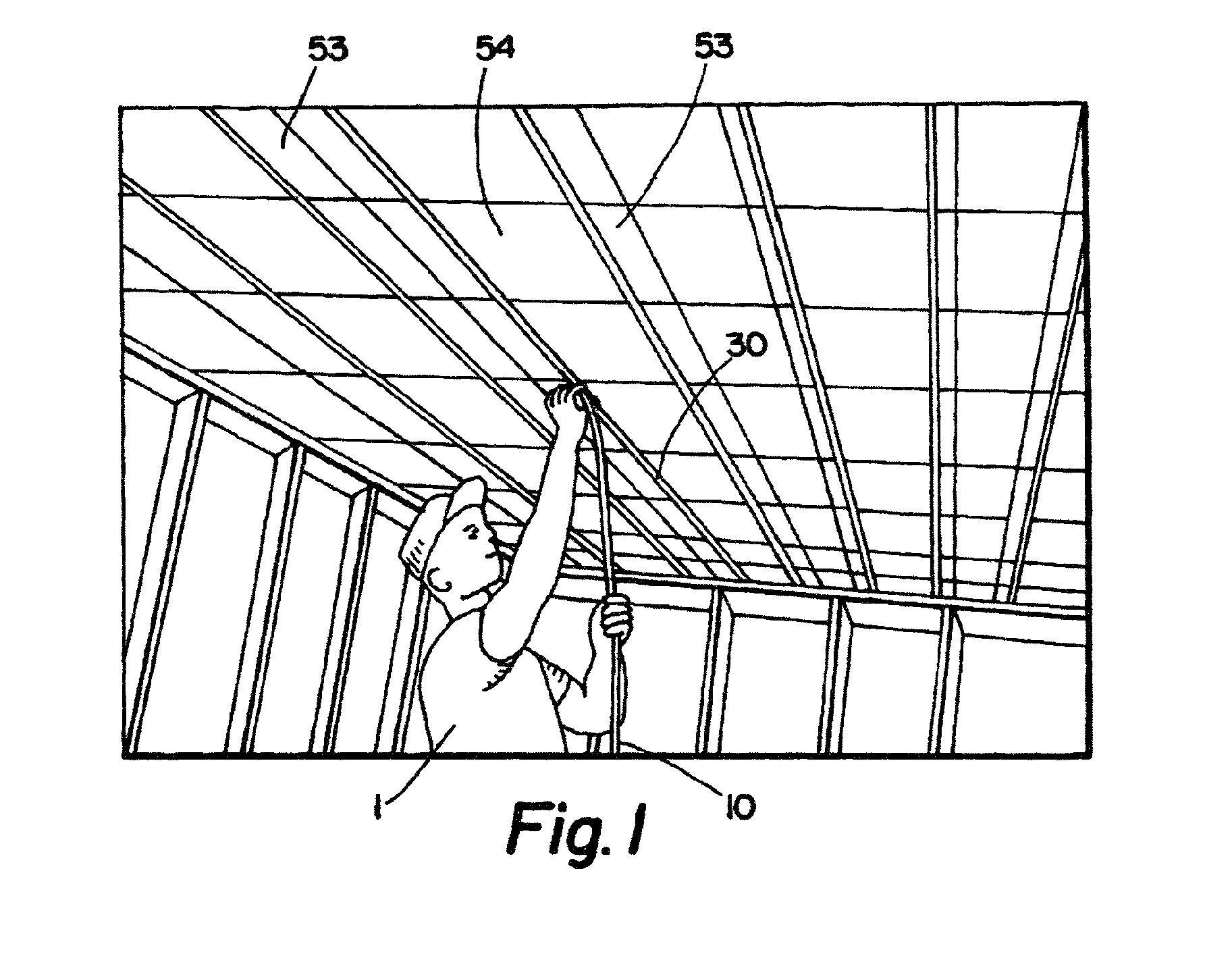
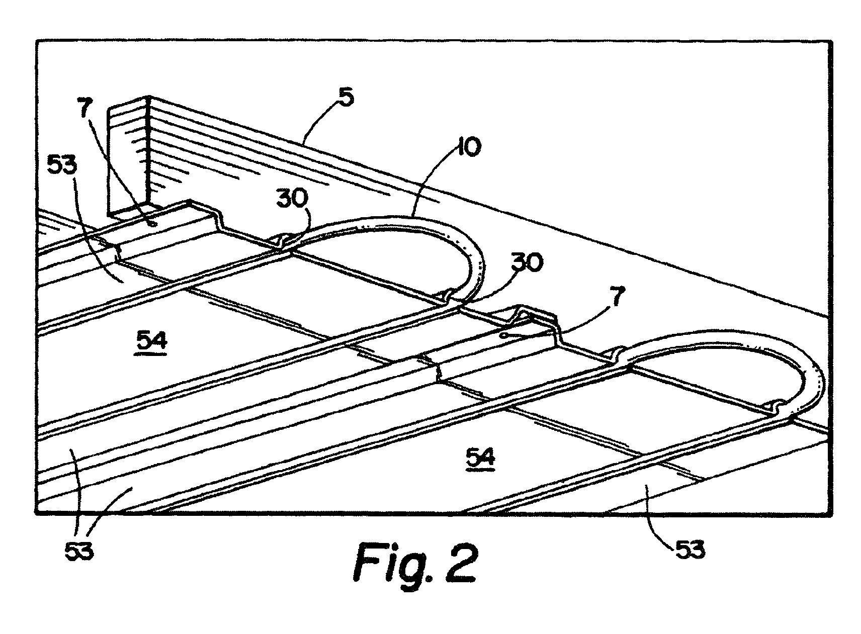
[0034]The applicant discloses a radiant plate comprising a portion offset from the joists or studs to which it is attached. A channel is disclosed within the offset space through which the hydronic tube is positioned.

[0035]Referring now to FIG. 1, an installer 1 is depicted in a living space easily threading a hydronic tube 10 into a channel 30. In this case the hydronic tube in use is Hydronic Alternatives ½″ PEOC-PLUS PE-RT 5-layered heating pipe with oxygen barrier, but any type of hydronic tubing could be installed just as easily and without departing from the spirit of the invention.

[0036]Referring now to both FIG. 1 and FIG. 2 for purposes of clarity, a series of parallel radiant plates (not numbered) is depicted, each comprising a flat center 54 and two flat edges 53. The radiant plates are better depicted in ...


PUM


Abstract

A radiant panel for use in radiant heating and cooling systems that provides numerous benefits over conventional panels currently in use. The radiant panel comprises an offset hydronic radiant tube channel in which is nested a hydronic radiant tube that obviates the need to thread the hydronic tubes through the joists in a ceiling installation or the studs in a wall installation. In an alternative embodiment, specific emissivity coatings on each side of the radiant panel further promote the efficient transfer of heat. The system provides increased sound isolation and is robust enough to withstand the crushing forces associated with a floor installation.

Description

RELATED APPLICATION[0001]This application is based on provisional application 60 / 926,457, filed Apr. 27, 2007.FIELD OF THE INVENTION[0002]The present invention relates to radiant heating and cooling systems, specifically the structure of radiant heating and cooling system panels.GENERAL BACKGROUND OF THE INVENTION[0003]Hydronic radiant heating is one of the oldest known forms of floor heating in the world, having its origins in ancient Rome. Radiant heating came into widespread use in the U.S. during the post-World War II building boom. Modern radiant systems include underfloor heating systems, wall-heating systems, and radiant ceiling systems.[0004]Conventional household heating and cooling systems are based on forced convection heating, wherein system-generated air convection currents circulate through the home and regulate air temperature. Radiant heating and cooling systems utilize the principle of radiant heat transfer a more efficient form of transferring heat.[0005]The earth ...

Claims


Application Information

Patent Timeline
Patent Type & Authority Patents(United States)
IPC IPC(8): F24D3/12F24D3/16F24D3/14
CPCF24D3/165F28F1/22Y02B30/00
Inventor NEWBERRY, DEAN TALBOTT
Owner TALBOTT SOLAR & RADIANT HOMES
Why Eureka
Try Eureka