Magnetic resonance imaging apparatus and magnetic resonance spectroscopic image computing method

a magnetic resonance imaging and computing method technology, applied in the field of magnetic resonance imaging technology, can solve the problems of difficult to improve spatial resolution and time resolution, low signal-to-noise ratio (hereinafter, snr), etc., and achieve the effect of short time and high accuracy

Active Publication Date: 2012-09-04
FUJIFILM HEALTHCARE CORP
View PDF8 Cites 4 Cited by
  • Summary
  • Abstract
  • Description
  • Claims
  • Application Information

AI Technical Summary

Benefits of technology

[0016]According to the present invention, in a MRSI measurement using a magnetic resonance imaging apparatus provided with a MAC, it is possible to obtain a magnetic resonance spectroscopic image, to which a MAC summation is applied with high accuracy and in short time, even though phase characteristic distribution of MAC has a spatial non-uniformity.

Problems solved by technology

However, a concentration of each metabolite is often very low so that the signal to noise ratio (hereinafter, called SNR) becomes low.
Therefore, it is difficult to improve spatial resolution and time resolution.
This makes it difficult to separate and extract a metabolite signal and therefore, a pre-processing for suppressing water signal is performed immediately before execution of usual excitation and detection.
However, in the MRSI, a low SNR, in measuring metabolite, makes SNR of signals acquired by the water-suppressed measurement low.
That results in reducing the phase correction accuracy.

Method used


Image

  • Magnetic resonance imaging apparatus and magnetic resonance spectroscopic image computing method
  • Magnetic resonance imaging apparatus and magnetic resonance spectroscopic image computing method
  • Magnetic resonance imaging apparatus and magnetic resonance spectroscopic image computing method

Examples


example

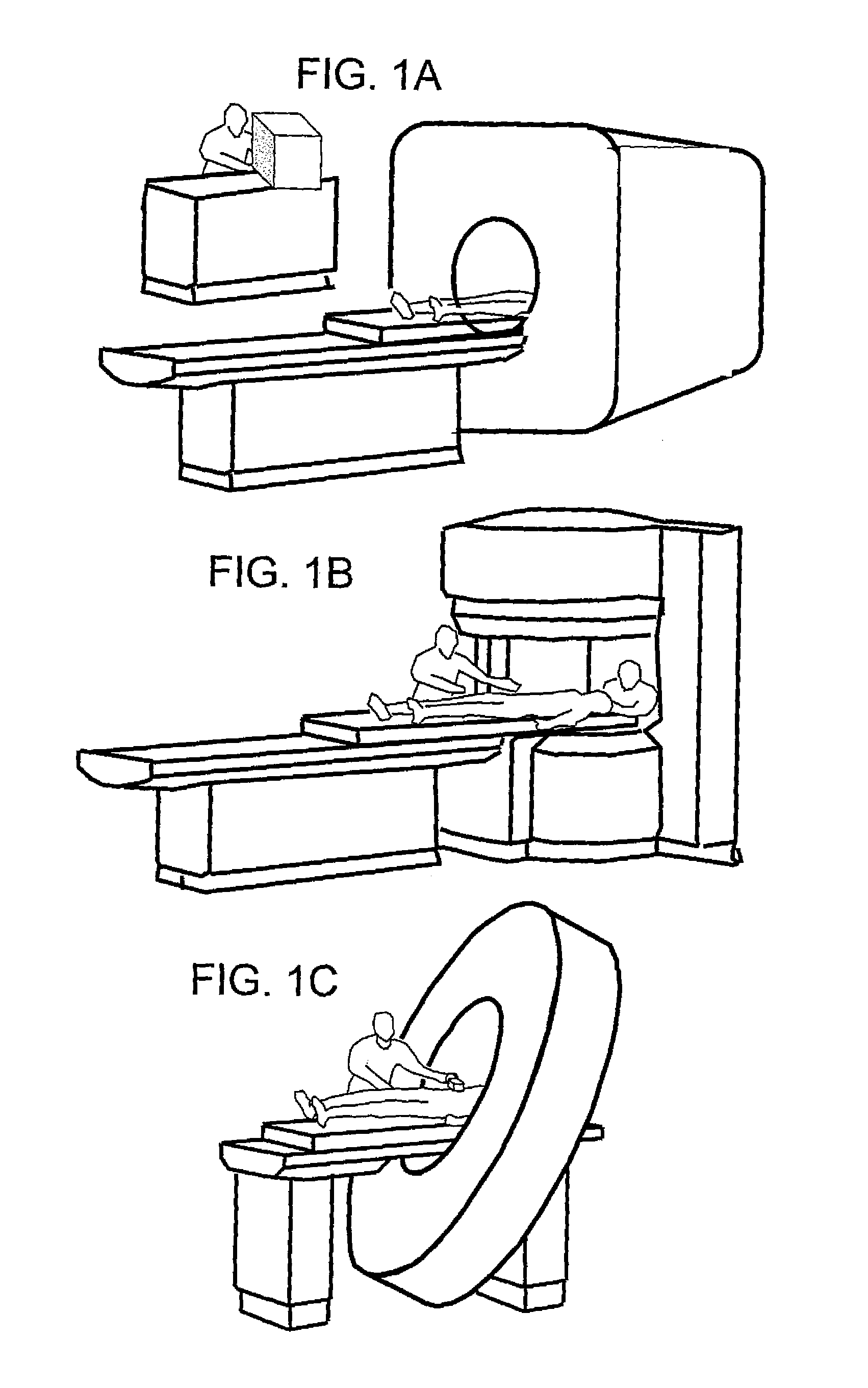
[0108]Examples of the first embodiment and the second embodiment are shown below. Here, the pulse sequences shown in FIG. 5 and FIG. 4 was executed as the MRSI measurement, using the magnetic resonance imaging apparatus of the type shown in FIG. 1A equipped with a multi-array coil (cylindrical coil) shown in the FIG. 3, where an intensity of the static magnetic field is 1.5 tesla. A target nuclide was a proton, and a target subject for measurement was a phantom fulfilled with a water solution of N-acetylealanine.

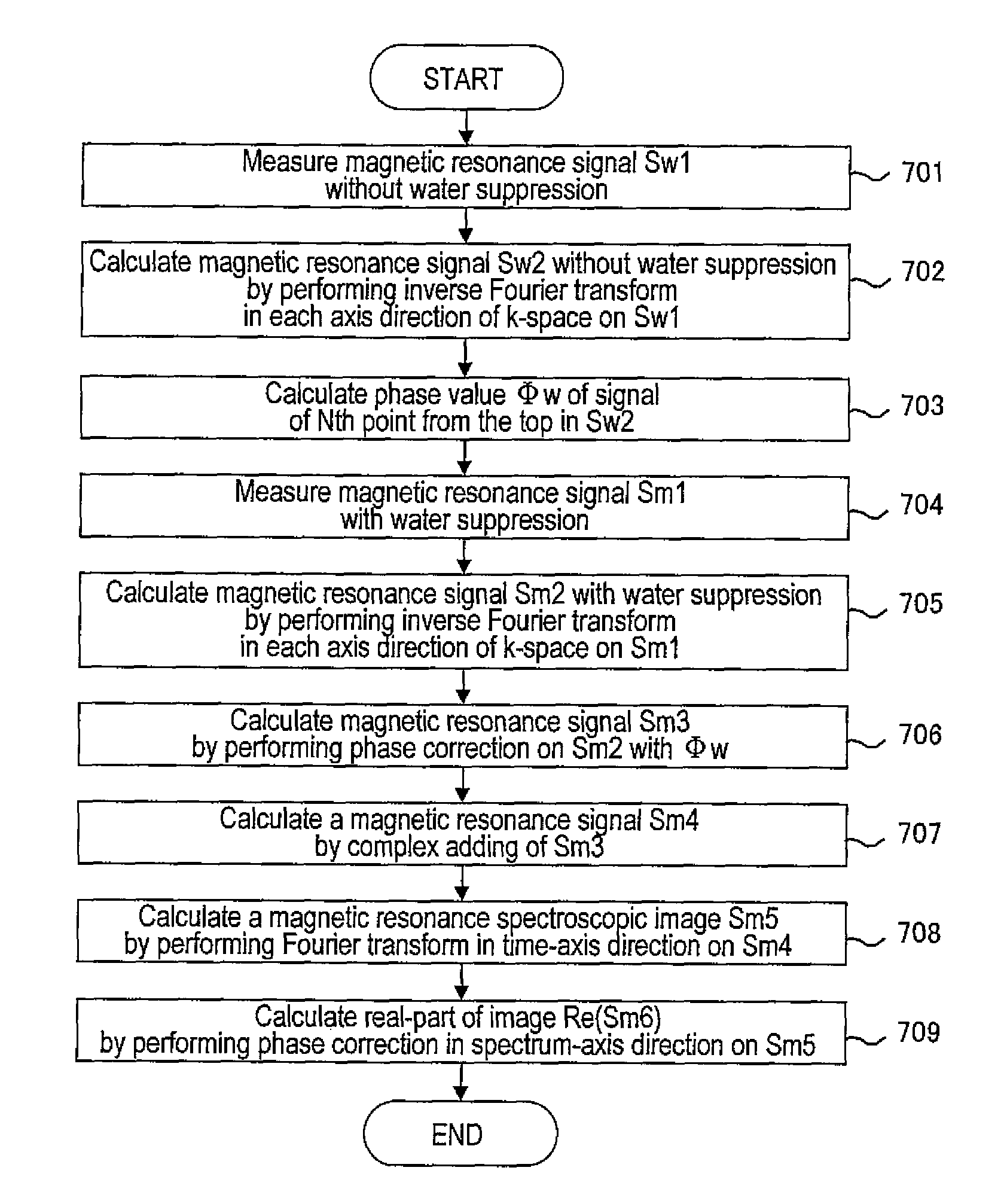
[0109]FIG. 10 shows a resultant spectroscopic image after the MAC summation was applied. FIG. 10A shows a result where the MAC summation was applied according to the procedure shown in FIG. 6, and FIG. 10B shows a result where the MAC summation was applied according to the procedure shown in FIG. 8. In both images, inside a selective excitation region is depicted as a uniform signal area in general, and this means that summed images having a uniform intensity distribution re...


PUM


Abstract

An object of the invention is to obtain a magnetic resonance spectroscopic image to which the MAC summation is applied with high accuracy and in short time, even though a phase characteristic distribution of the MAC has a spatial non-uniformity, in the MRSI measurement using a magnetic resonance imaging apparatus provided with a MAC. Using a non-water-suppressed image signal with high SNR, obtained in the non-water-suppressed measurement (a reference measurement) without water suppression, a correction value for correcting the phase distortion for the MAC summation is calculated on each pixel in each coil. After correcting a phase on each pixel in each coil of a main-scan image signal measured under suppressing water (water-suppressed image signal) using the corrective value, signal adding operation (summation) is performed. Then, a phase correction in a spectrum-axis is to be performed on the summed spectrum signal.

Description

TECHNICAL FIELD[0001]The present invention relates to a magnetic resonance imaging technology, or more particularly to an apparatus and a method suitable for obtaining of a magnetic resonance spectroscopic image.BACKGROUND ART[0002]A magnetic resonance imaging apparatus irradiates a radiofrequency magnetic field at specific frequency to a subject placed in a static magnetic field, so as to excite nuclear magnetization of each nucleus of hydrogen or the like contained in the subject and to detect a magnetic resonance signal generated from the subject and thereby acquiring physical / chemical information. In addition to a magnetic resonance imaging (hereinafter abbreviated as MRI) now in widespread use, a magnetic resonance spectroscopic imaging (herein after abbreviated MRSI), which separates magnetic resonance signals to be rendered as images every molecules with a base as to the difference (hereinafter called chemical shift) among resonant frequencies due to the difference among chem...

Claims


Application Information

Patent Timeline
Patent Type & Authority Patents(United States)
IPC IPC(8): G01V3/00
CPCA61B5/055A61B5/7257
Inventor HIRATA, SATOSHIBITO, YOSHITAKATANAKA, KIYOHARU
Owner FUJIFILM HEALTHCARE CORP
Why Eureka
Try Eureka