
Electronic device with heating protection circuit and heating protection method thereof

a technology of heating protection circuit and electronic device, applied in the field of electronic devices, can solve problems such as failure to operate the whole system successfully

Active Publication Date: 2012-09-11
PEGATRON
View PDF22 Cites 22 Cited by
  • Summary
  • Abstract
  • Description
  • Claims
  • Application Information

AI Technical Summary

Benefits of technology

[0008]This invention provides an electronic device, capable of using a heating protection circuit to prevent unconditional heating caused by a malfunction of a heating signal or abnormity of a power source of a control element from burning down a heating device or a heated element, and a method thereof to improve the prior art.
[0012]Compared with the prior art, according to the electronic device with the heating protection circuit and the method thereof in the invention, a control signal CTL generated by the control module can assist the heating protection circuit in correctly determining whether a heating signal is failed (for example, the failed state may be caused by errors of a firmware program) or whether a control voltage of a control element is abnormal, thus to automatically control the heating module to stop heating. Therefore, the problem that a heating film or a heated element may be burnt down caused by unconditional heating and failure of stopping heating in the prior art can be effectively avoided, such that the whole system can be successfully booted up and operated under a lower temperature.

Problems solved by technology

However, since the present industrial computer with the lower temperature booting function can control switches of the control element responsible for heating only via firmware, once a heating signal has a malfunction (for example, the malfunction may be caused by errors of a firmware program) or a control voltage of the control element is abnormal, the control element may control a heater continually to heat to make a heating film or a heated element may be burnt down, such that the whole system fails to be operated successfully.

Method used


Image

  • Electronic device with heating protection circuit and heating protection method thereof
  • Electronic device with heating protection circuit and heating protection method thereof
  • Electronic device with heating protection circuit and heating protection method thereof

Examples


first embodiment

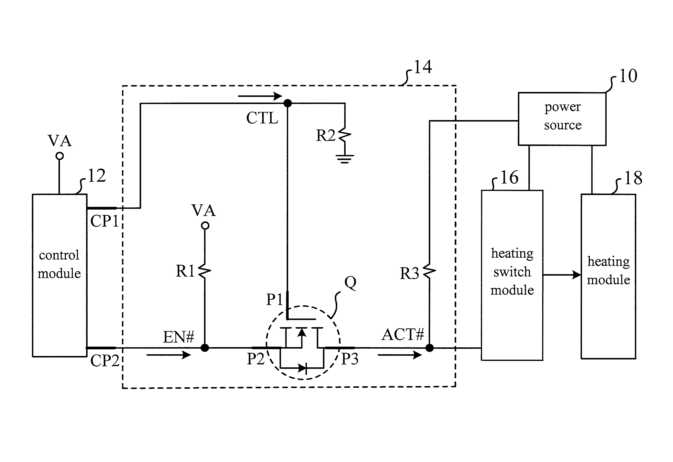
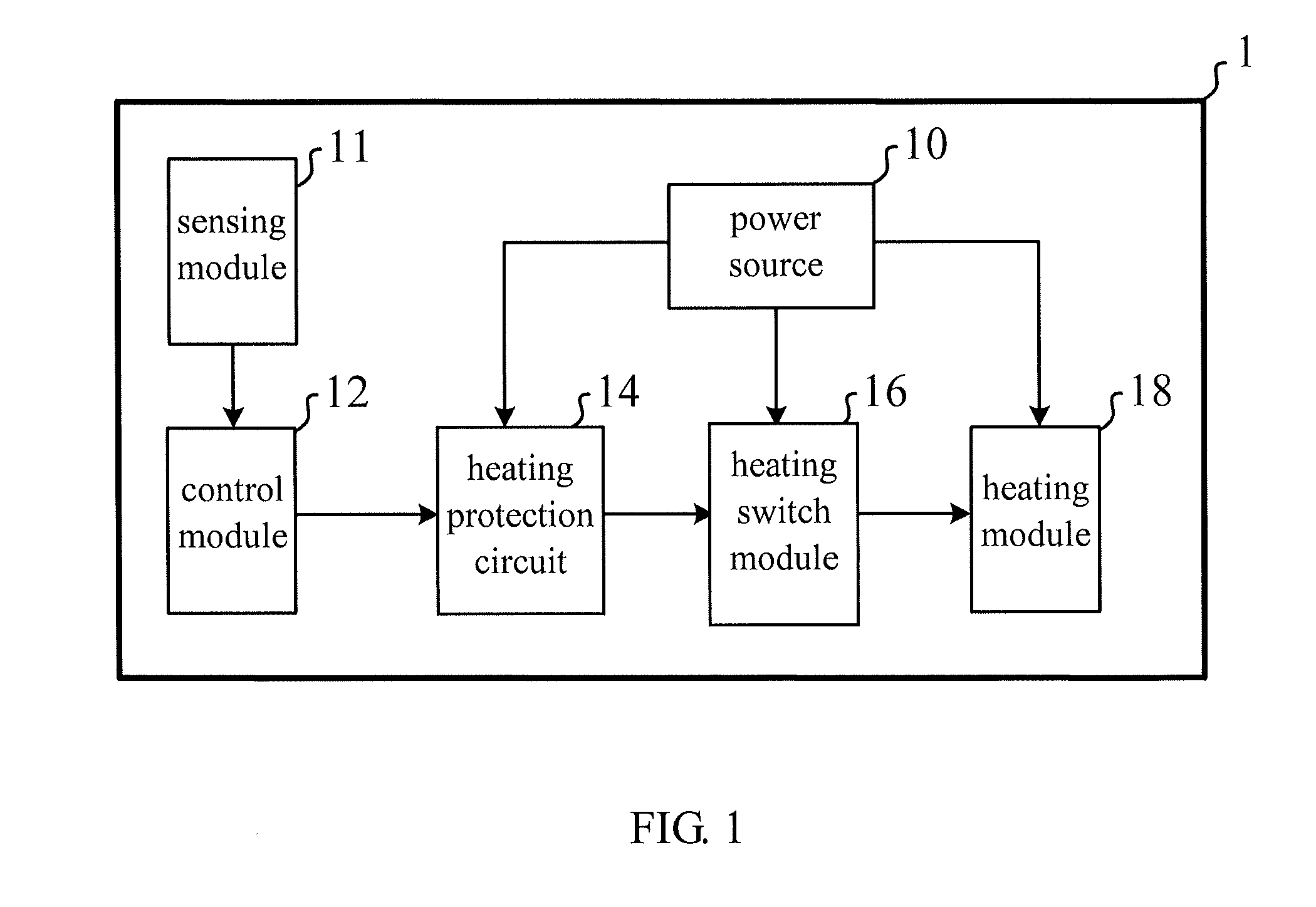
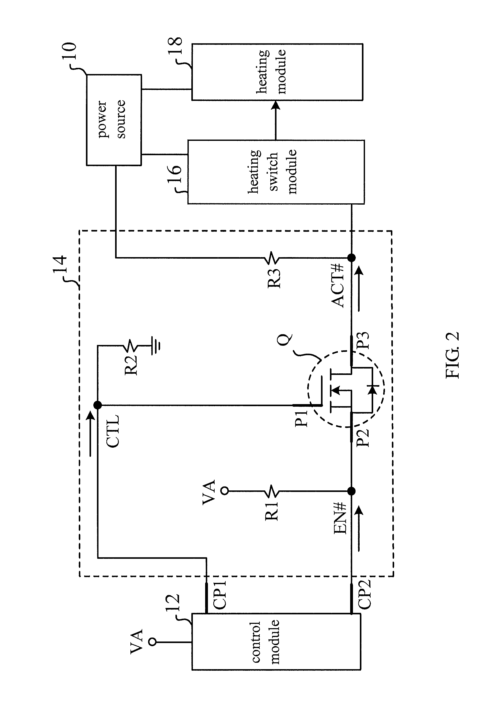
[0018]According to the invention, an electronic device is provided. The electronic device in this embodiment may be an industrial computer with a lower temperature booting specification and function. However, the invention is not limited thereto. FIG. 1 is a functional block diagram showing an electronic device 1 according to the embodiment. FIG. 2 is a detailed circuit diagram showing a heating protection circuit 14 of the electronic device 1 in FIG. 1.

[0019]Please refer to FIG. 1 and FIG. 2 together. The electronic device 1 includes a power source 10, a sensing module 11, a control module 12, a heating protection circuit 14, a heating switch module 16, and a heating module 18. The power source 10 is coupled with the heating protection circuit 14, the heating switch module 16, and the heating module 18, and it is used for providing power needed by operation of each module. The sensing module 11 is coupled with the control module 12. The control module 12 is coupled with the heating...

second embodiment

[0038]According to the invention, a heating protection circuit is provided. The heating protection circuit is applied to an electronic device with a lower temperature booting function. The electronic device includes a power source, a control module, a heating switch module, and a heating module. The control module provides a first control signal and a second control signal via a plurality of control pins, respectively. The detailed circuit is shown in FIG. 2. Therefore, it is not described herein for a concise purpose.

[0039]In the embodiment, the heating protection circuit includes a heating protection unit, a first resistor, a second resistor, and a third resistor. The heating protection unit is coupled with the control module and the heating switch module, and it is used for receiving the first control signal and the second control signal from the control module and for generating a third control signal according to the first control signal and the second control signal thus to tr...

third embodiment

[0043]According to the invention, a heating protection method of an electronic device is provided. In the embodiment, the electronic device includes a control module, a heating protection circuit, a heating module, and a heating switch module. The control module has a first control pin and a second control pin. The heating protection circuit may include a heating protection unit, a first resistor, a second resistor, and a third resistor. The heating protection unit may be a MOSFET. However, the invention is not limited thereto.

[0044]FIG. 3 is a flowchart showing a heating protection method for operating the electronic device. In FIG. 3, in step S10, the control module provides a first control signal and a second control signal via the first control pin and the second control pin, respectively. In step S12, the heating protection circuit receives the first control signal and the second control signal from the first control pin and the second control pin and generates a third control ...


PUM

PropertyMeasurementUnit
control voltageaaaaaaaaaa
temperatureaaaaaaaaaa
operating temperatureaaaaaaaaaa

Abstract

This invention discloses an electronic device with a heating protection circuit and a heating protection method thereof. The electronic device includes a control module, a heating protection circuit, a heating switch module, and a heating module. The control module provides a first control signal and a second control signal via a plurality of control pins, respectively. The heating protection circuit generates a third control signal according to the first control signal and the second control signal. The heating switch module controls the heating module whether to heat according to the third control signal.

Description

CROSS-REFERENCE TO RELATED APPLICATIONS[0001]This Non-provisional application claims priority under 35 U.S.C. §119(a) on Patent Application No(s). 098117273 filed in Taiwan, Republic of China on May 25, 2009, the entire contents of which are hereby incorporated by reference.BACKGROUND OF THE INVENTION[0002]1. Field of the Invention[0003]This invention relates to an electronic device and, more particularly, to an electronic device with a heating protection circuit and a heating protection method thereof.[0004]2. Description of the Related Art[0005]In recent years, with development of electronic science, different kinds of data processing devices with different functions and uses, such as personal computers, notebook computers, and industrial computers, are presented at the market. The industrial computers are widely applied to different kinds of fields.[0006]Generally speaking, in response to different using environment, the industrial computers may have different corresponding speci...

Claims


Application Information

Patent Timeline
Patent Type & Authority Patents(United States)
IPC IPC(8): H05B3/02
CPCG06F1/20
Inventor YEN, HUNG-WEI
Owner PEGATRON
Learn More