Modular magnetron

a magnetron and module technology, applied in the field of magnetrons, can solve the problems of having to replace the magnetron in the assembly of the uv lamp, the magnet may fail, etc., and achieve the effect of reducing electromagnetic interferen

Inactive Publication Date: 2012-09-11
HERAEUS NOBLELIGHT AMERICA
View PDF3 Cites 10 Cited by
  • Summary
  • Abstract
  • Description
  • Claims
  • Application Information

AI Technical Summary

Benefits of technology

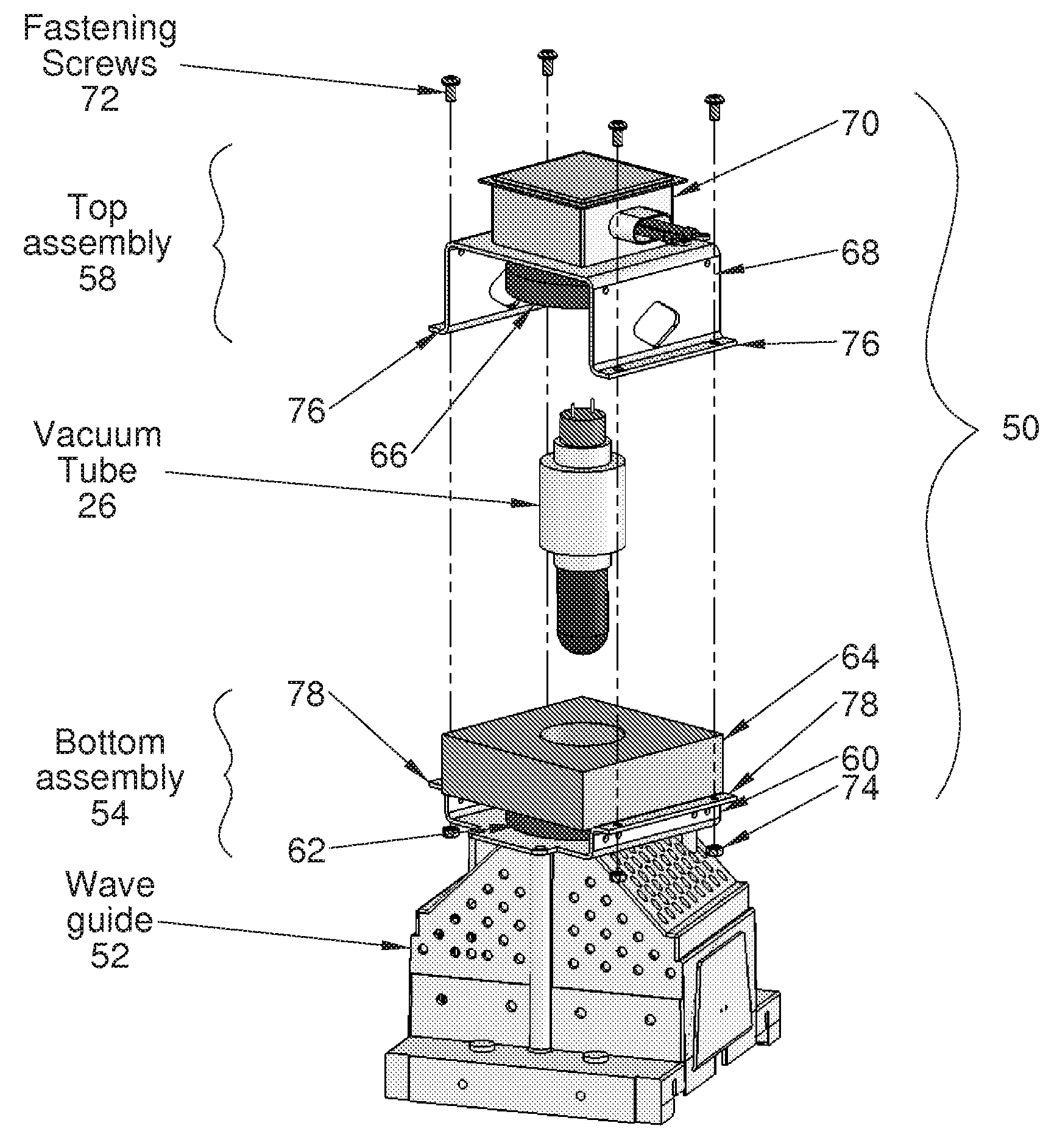
[0016]According to an embodiment of the present invention, the vacuum top further comprises a top portion with electrical connections extending therefrom, the electrical connections each having one of a push-on type connector and a screw-terminal connection that is accessible through the connection box. The vacuum tube is configured to be keyed within the bottom assembly so that the electrical connections of the vacuum tube mate with the connection box. The connection box includes filter elements to reduce electromagnetic interference. The bottom assembly is configured to be fastened to a waveguide, the waveguide having an opening for receiving an antenna dome of the vacuum tube, the antenna dome being configured to emit microwave radiation.

Problems solved by technology

In addition, a magnetron may fail and have to be replaced in a UV lamp assembly.

Method used


Image

  • Modular magnetron
  • Modular magnetron
  • Modular magnetron

Examples


Embodiment Construction

[0026]FIG. 4 shows a partial exploded perspective view and FIG. 5 is an assembled perspective view of a modular magnetron 50 mounted overlying a waveguide 52, according to an embodiment of the present invention. Referring now to FIGS. 4 and 5, the modular magnetron 50 includes a bottom assembly 54, a vacuum tube 26, and a top assembly 58. The bottom assembly 54 includes a bottom yoke 60, a bottom magnet 62, and cooling assembly 64. The top assembly 58 includes a top magnet 66, a top yoke 68, and a filter / connection box 70. In a preferred embodiment, the bottom assembly 54 and the top assembly 58 are configured as non-disposable units. The vacuum tube 26 is configured to be replaced during routine maintenance or a vacuum tube failure.

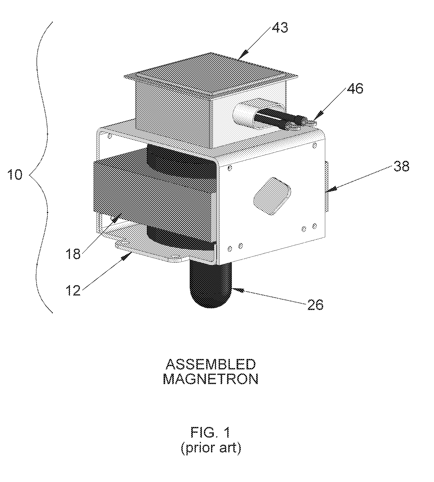
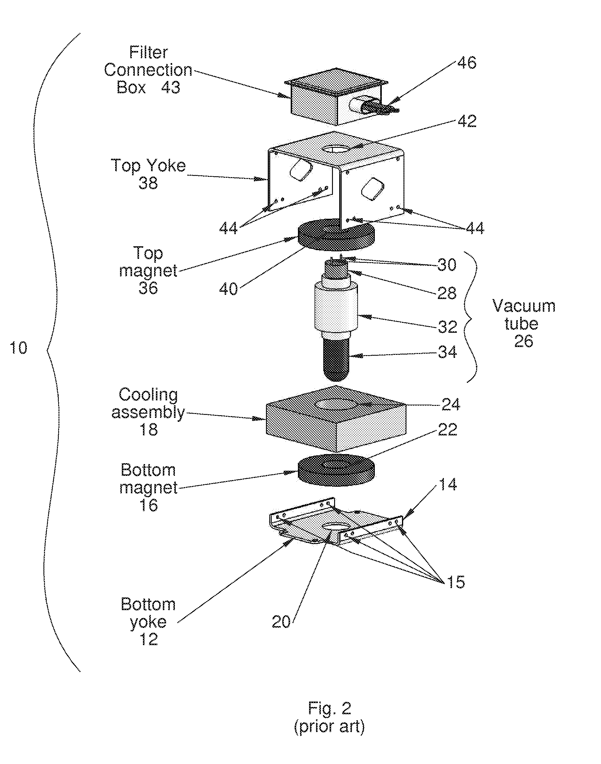
[0027]The bottom assembly 54 is adapted to be mounted overlying the waveguide 52 in a way similar to the prior art (non-modular) magnetron of FIGS. 1 and 2, using screws and the original mounting holes (not shown) on the waveguide. According to a preferr...


PUM

PropertyMeasurementUnit
thermalaaaaaaaaaa
electrical conductivityaaaaaaaaaa
outer diameteraaaaaaaaaa

Abstract

A modular magnetron for use in UV curing lamp assembly is disclosed. The modular magnetron includes a vacuum tube having a vacuum tube body, a top assembly, and a bottom assembly. The top assembly is configured to substantially overlay the vacuum tube. The bottom assembly is configured to substantially extend about the vacuum tube, the vacuum tube being positioned to partially protrude from the bottom assembly, the bottom assembly including a cooling assembly configured to employ a flexible clamp-type fitting about the vacuum tube body for substantially maintaining thermal and electrical conductivity. The top assembly is configured to be releasably fastened to the bottom assembly about the vacuum tube with removable fasteners.

Description

FIELD OF THE INVENTION[0001]The invention relates generally to magnetrons, and more particularly, to a modularly assembled magnetron for use in ultraviolet radiation (UV) curing lamp assemblies.BACKGROUND OF THE INVENTION[0002]Radiant energy is used in a variety of manufacturing processes to treat surfaces, films, and coatings applied to a wide range of materials. Specific processes include but are not limited to curing (i.e., fixing, polymerization), oxidation, purification, and disinfection. Processes using radiant energy to polymerize or effect a desired chemical change is rapid and often less expensive in comparison to a thermal treatment. The radiation can also be localized to control surface processes and allow preferential curing only where the radiation is applied. Curing can also be localized within the coating or thin film to interfacial regions or in the bulk of the coating or thin film. Control of the curing process is achieved through selection of the radiation source t...

Claims


Application Information

Patent Timeline
Patent Type & Authority Patents(United States)
IPC IPC(8): H01J25/50
CPCH01J23/005H01J25/50Y10T29/4902H01J65/044
Inventor LEONHARDT, DARRIN
Owner HERAEUS NOBLELIGHT AMERICA
Why Eureka
Try Eureka