Shared memory multi video channel display apparatus and methods

a video channel display and multi-video technology, applied in the field of shared memory multi-video channel display apparatus and methods, can solve the problems of achieve the effects of reducing memory access bandwidth, high-quality video channels, and reducing overall memory bandwidth and capacity requirements

Active Publication Date: 2012-09-11
SYNAPTICS INC +1
View PDF63 Cites 5 Cited by
  • Summary
  • Abstract
  • Description
  • Claims
  • Application Information

AI Technical Summary

Benefits of technology

[0015]In accordance with the principles of the present invention systems and methods are provided for reducing memory access bandwidth in various sections of one or more video pipeline stages of one or more channels in order to produce a display having multiple high quality video channel streams.
[0017]In accordance with the principles of the present invention, methods and apparatus are provided for reducing memory access bandwidth in various sections of one or more video pipeline stages of one or more channels in order to produce a display having multiple high-quality video channel streams. A dual video processor may receive one or more analog or digital signals which may be in different formats. A dual video decoder (e.g., NTSC / PAL / SECAM video decoder) capable of decoding two simultaneous video signals in one or more video modes may be provided. In one of the video modes, the dual video decoder may perform time multiplexing to share at least one component such as an analog to digital converter, used in decoding the video signals.
[0018]The outputs of the video decoder, or another set of video signals provided by another component in the system, may be provided to signal processing circuitry (e.g., a noise reducer and / or a de-interlacer). The signal processing circuitry may access a memory device to store various field lines. Some of the stored field lines, that may be needed by the signal processing circuitry, may be shared. The sharing of some stored field lines reduces overall memory bandwidth and capacity requirements. The signal processing circuitry may be capable of performing multiple field line processing. A set of field line buffers may be provided to store field lines for multiple field segments and may provide the data to the corresponding inputs of the signal processing circuitry. To further reduce storage, some of the field line buffers may also be shared among the signal processing circuitry.
[0019]The outputs of the video decoder, or another set of video signals provided by another component in the system, may be provided to one or more scalers for producing differently scaled video signals. The scaler may be configured to be placed in various slots before the memory, after the memory, or if no memory access is desired either before or after (i.e., between the memory). If a video signal is to be up-scaled, the scaler may be placed after the memory in order to reduce the amount of data that is stored to the memory. If a video signal is to be downscaled, the scaler may be placed before the memory in order to reduce the amount of data that is stored to the memory. Alternatively, one scaler may be configured to be placed before the memory while another scaler may be configured to be placed after the memory thereby providing two video signals that are scaled differently (i.e., one may be up-scaled while the other may be downscaled) while reducing the amount of memory storage and bandwidth.
[0020]The outputs of the video decoder, or another set of video signals provided by another component in the system, may be provided to one or more frame rate conversion units. A blank time optimizer (BTO) may receive data pertaining to a field line of a frame of a video signal at a first clock rate. The BTO may determine the maximum amount of time available before the next field line of the frame is received. Based on this determination the BTO may send or receive the field line of the frame to memory at a second clock rate. The second clock rate used for the memory access may be substantially slower than the first, thereby reducing memory bandwidth and enabling another video signal that may have a shorter amount of available time between field lines to access memory faster. In turn, the BTO essentially distributes memory access from several memory clients (i.e., units requiring memory access) in a way that promotes efficient use of the memory bandwidth.

Problems solved by technology

The sharing of some stored field lines reduces overall memory bandwidth and capacity requirements.

Method used


Image

  • Shared memory multi video channel display apparatus and methods
  • Shared memory multi video channel display apparatus and methods
  • Shared memory multi video channel display apparatus and methods

Examples


Embodiment Construction

[0044]The invention relates to methods and apparatus for reducing memory access bandwidth and sharing memory and other processing resources in various sections of multiple video pipeline stages of one or more channels in order to produce one or more high-quality output signals.

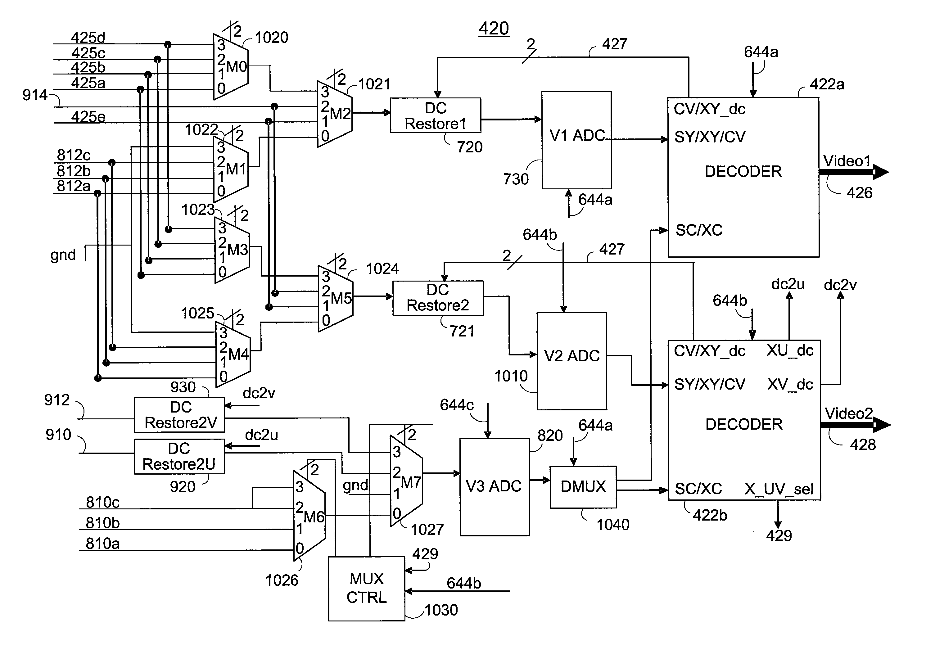
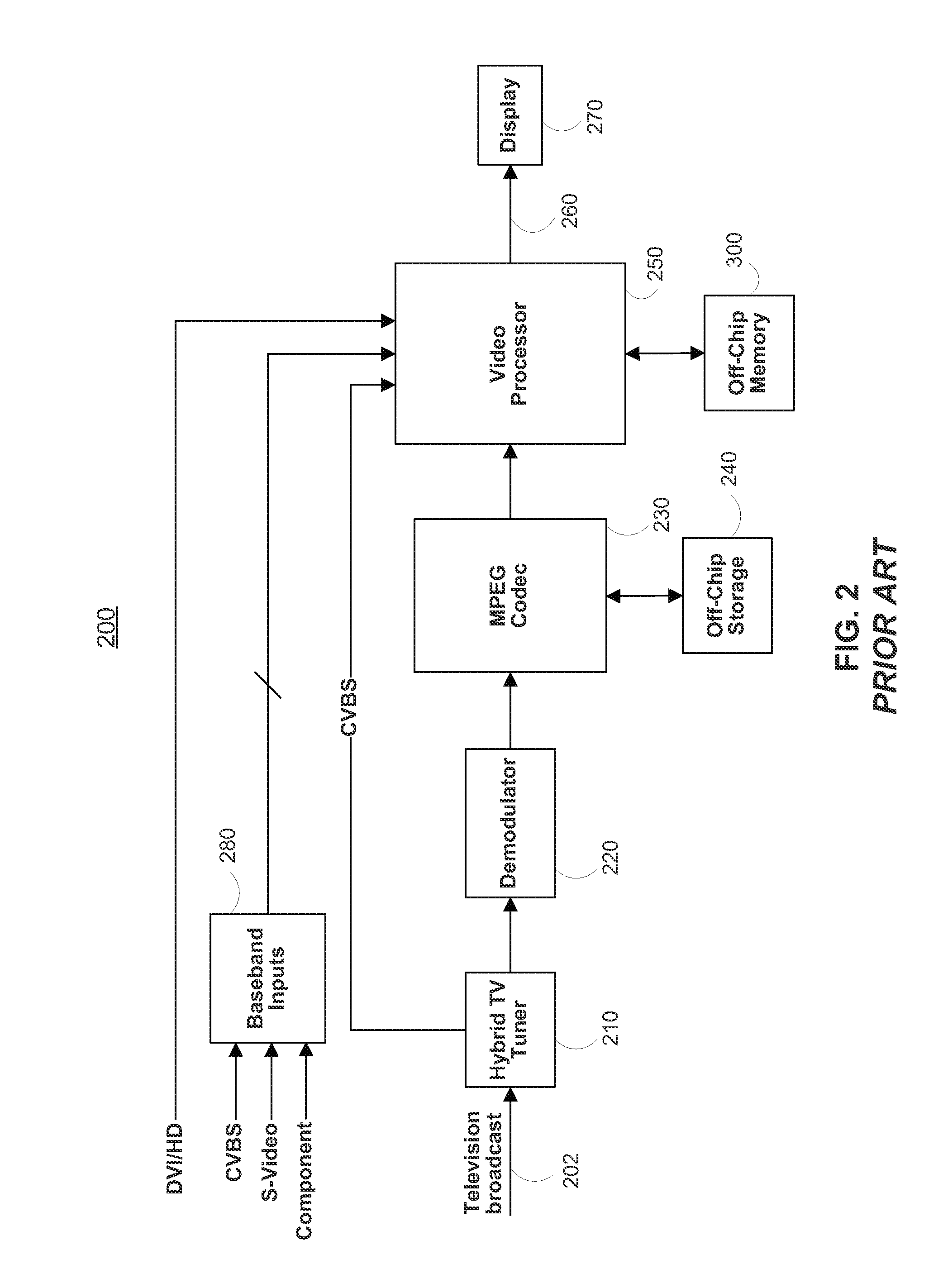
[0045]FIG. 4 illustrates a television display system in accordance with the principles of the present invention. The television display system depicted in FIG. 4 may include, television broadcast signals 202, a dual tuner 410, MPEG Codec 230, off-chip storage 240, off-chip memory 300, a dual video processor 400, a memory interface 530 and at least one external component 270. Dual tuner 410 may receive television broadcast signals 202 and produce a first video signal 412 and a second video signal 414. Video signals 412 and 414 may then be provided to a dual decoder 420. Dual decoder 420 is shown to be internal to dual video processor 400, but may alternatively be external to video processor 400. Dual decoder 42...


PUM


Abstract

The invention includes a system and the associated method for decoding multiple video signals. The video signals may be component video, composite video or s-video signals each having multiple portions using a multimode video decoder. A selection stage may combine the multiple video signals and select some of their video signal portions for processing. The selection stage may time-multiplex some of the video signal portions. An analog to digital conversion stage may be shared by the time-multiplexing of the video signals. A decoder stage may decode the various signal portions and provide decoded output video signals. These feature may reduce the overall cost of the system. Various clock signals may be used to operate various stages of a multimode video decoder. Some of the clock signals may run at different frequencies and others may operate at a different phase.

Description

CROSS REFERENCE TO RELATED APPLICATION[0001]This application claims the benefit of U.S. Provisional Applications Nos. 60 / 793,288, filed Apr. 18, 2006, 60 / 793,276, filed Apr. 18, 2006, 60 / 793,277, filed Apr. 18, 2006, and 60 / 793,275, filed Apr. 18, 2006 each disclosure of which is hereby incorporated by reference herein in its entirety.BACKGROUND OF THE INVENTION[0002]Traditionally, multi video channel television display screens are equipped with dual channel video processing chips which enable a user to view one or more channels simultaneously on various portions of the display screen. This form of displaying a picture within a picture is commonly referred to as picture-in-picture or PIP. FIG. 1A is an example of displaying two channels on various portions of the display screen having an aspect ratio of 4:3. A screen 100A displays a first channel 112 on the majority portion of the screen simultaneously with a second channel 122 that is displayed on a substantially smaller portion of...

Claims


Application Information

Patent Timeline
Patent Type & Authority Patents(United States)
IPC IPC(8): H04N5/50H04N21/426H04N21/438
CPCH04N5/45H04N5/455H04N21/42638H04N21/4305H04N21/4347H04N21/4316H04N21/4435H04N21/440263H04N21/440281G09G5/14G09G5/36G09G5/39
Inventor GARG, SANJAYGHOSH, BIPASHABALRAM, NIKHILSRIDHAR, KAIPSAHU, SHILPITAYLOR, RICHARDEDWARDS, GWYNTOMASI, LORENNAMBOODIRI, VIPIN
Owner SYNAPTICS INC
Why Eureka
Try Eureka