Munitions endgame geometry for optimal lethality system

a technology of endgame geometry and optimal lethality, applied in the field of airborne munitions asset onboard system, can solve the problems of high kill probability, and achieve the effect of increasing kill probability, high kill probability, and high kill probability

Inactive Publication Date: 2012-09-18
SURVICE ENG
View PDF5 Cites 8 Cited by
  • Summary
  • Abstract
  • Description
  • Claims
  • Application Information

AI Technical Summary

Benefits of technology

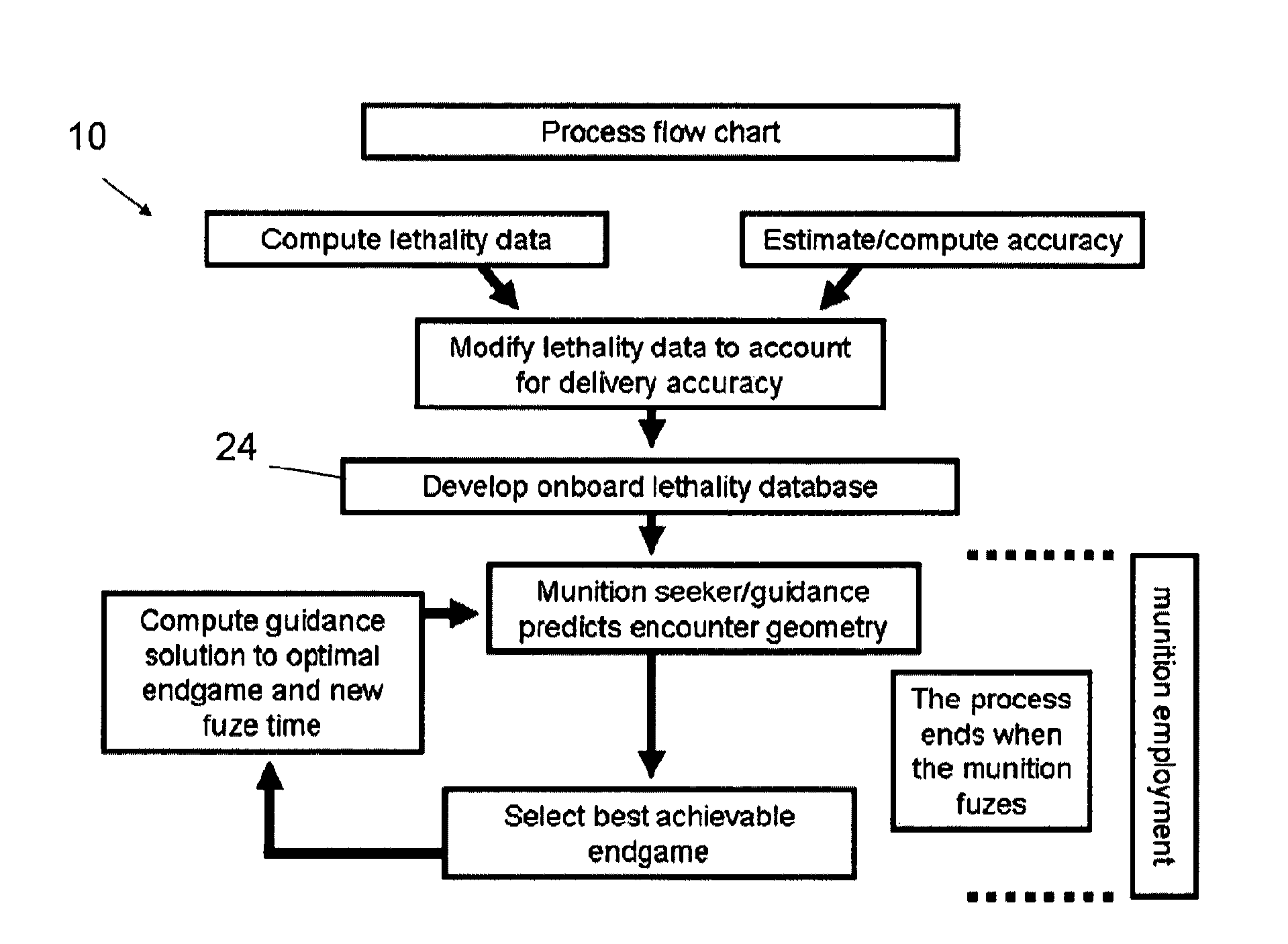
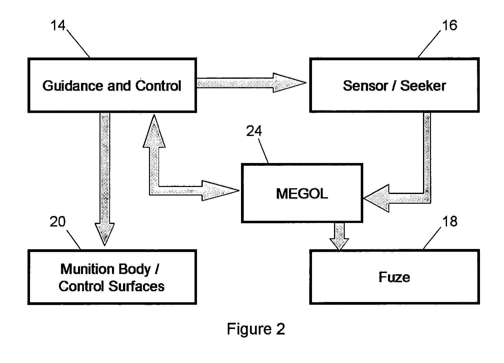
[0011]The munitions endgame geometry for optimal lethality system of the present invention addresses the aforementioned needs in the art by providing an onboard system for a weapon that allows the weapon, based on the determination of target type, the target class or the target subclass, to determine the vulnerabilities of the target in order to allow the weapon to achieve a desired position, orientation, and velocity at detonation so as to increase the probability of kill by the weapon of the target. The munitions endgame geometry for optimal lethality system continually updates during fly out in order to accommodate velocity and position changes of the target as well as the flight dynamics of the weapon. For example, should a desired azimuth and elevation angle at detonation no longer be achievable due to change of position of the target and the proximity of the weapon to the target, the munitions endgame geometry for optimal lethality system recalculates in order to determine the optimal endgame geometry that is achievable under the current real-time conditions. Additionally, if the recalculated endgame geometry that is achievable is insufficient to achieve a high probability of kill, the munitions endgame geometry for optimal lethality system is able to guide the weapon to a revised target should the munitions endgame geometry for optimal lethality system determine that the achievable endgame geometry for the revised target can result in a higher probability of kill. Due to the incredibly small size of modern electronic circuits, and such circuits' abilities to effect incredibly fast computational speeds, the munitions endgame geometry for optimal lethality system does not occupy undue space or weight within the overall weapon. In fact, the entire MEGOL system can be implemented within an existing munition's operational flight program and memory, in some cases requiring no additional hardware or weight.
[0012]The munitions endgame geometry for optimal lethality system allows a battlefield commander to deploy small autonomous weapons able to independently prosecute a wider target set, and capable of achieving a high probability of kill, thereby reducing the potential for collateral damage and non-combatant deaths as well as allowing the commander to stock a relatively high number of weapons onto a given delivery vehicle.

Problems solved by technology

Additionally, if the recalculated endgame geometry that is achievable is insufficient to achieve a high probability of kill, the munitions endgame geometry for optimal lethality system is able to guide the weapon to a revised target should the munitions endgame geometry for optimal lethality system determine that the achievable endgame geometry for the revised target can result in a higher probability of kill.

Method used


Image

  • Munitions endgame geometry for optimal lethality system
  • Munitions endgame geometry for optimal lethality system
  • Munitions endgame geometry for optimal lethality system

Examples


Embodiment Construction

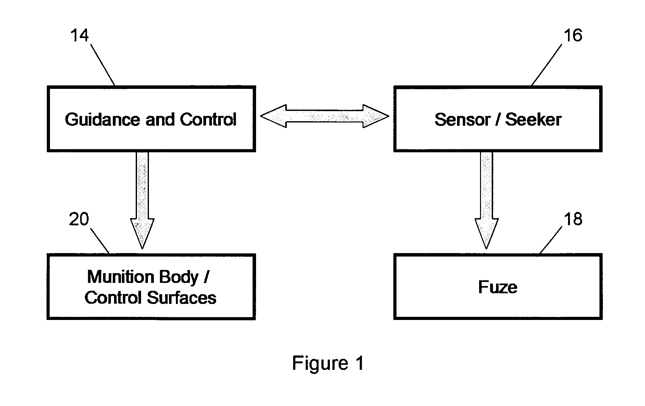
[0023]Referring now to the drawings, it is seen that the munitions endgame geometry for optimal lethality system (MEGOL) of the present invention, generally denoted by reference numeral 10, is comprised of a system that is integrated into the on-board control circuitry of an airborne munition 12 of any appropriate type, including air-to-surface, air-to-air, surface-to-air, surface-to-surface, anit-ship, and anti-satellite munitions. As seen in FIG. 1, a typical modern day “smart” weapon has four major components that are used for the desired delivery of the weapon 12, the guidance system 14, the sensor system 16, the fuze system 18, and the flight controls 20 that control fly out operations of the weapon 12. These systems operate to bring the weapon 12 to a moving target 22 and attempt to deliver the weapon to the center of the target 22 with the munition on board the weapon 12 being fuzed in some preprogrammed fashion (which may or not be impact, or timed or computed via a separate...


PUM


Abstract

A system that guides an airborne weapon toward a target, in order for the weapon to fuze at the target, so as to increase the probability of kill of the target. The system uses a lethality database that lists the various vulnerabilities for each target so that the weapon may fuze at a point that achieves maximum exploitation of the vulnerabilities. The system continually updates during weapon fly out in order to continually update the best achievable aim point for the weapon based on the changing encounter geometry between weapon and target.

Description

[0001]This application claims the benefit of provisional patent application No. 60 / 940,234 filed on May 25, 2007, which provisional application is incorporated herein by reference.STATEMENT REGARDING FEDERALLY SPONSORED RESEARCH OR DEVELOPMENT[0002]This material is based upon work supported by the United States Air Force under Contract No. FA8651-07-C-0096.Distribution B.Distribution authorized to US Government agencies only, contains proprietary information, 29 Jan., 2007. Refer other requests for this document to AFRL / MNMF, Eglin AFB Florida32542-6810.Warning[0003]This document contains technical data whose export is restricted by the Arms Export Control Act (Title 22, U.S.C. 2751 et seq) or the Export Administration Act of 1979, as amended, Title 50, U.S.C., App. 2401 et seq. Violation of these export-control laws is subject to severe criminal penalties. Dissemination of this document is controlled under DoD DirectiveBACKGROUND OF THE INVENTION[0004]1. Field of the Invention[0005...

Claims


Application Information

Patent Timeline
Patent Type & Authority Patents(United States)
IPC IPC(8): F42C17/00
CPCF42C11/002
Inventor LARSON, CHARLES ALLENMCARDLE, KEVIN THOMAS
Owner SURVICE ENG
Why Eureka
Try Eureka