Method for dynamic road mapping

a dynamic road mapping and mapping method technology, applied in the field of dynamic road mapping of the vascular system, can solve the problems of difficult task of guiding and positioning the catheter, preventing the effective use of the catheter, and insufficient enhanced 2d images, etc., and achieve the effect of better catheter guidan

Inactive Publication Date: 2012-09-18
SIEMENS HEALTHCARE GMBH
View PDF5 Cites 59 Cited by
  • Summary
  • Abstract
  • Description
  • Claims
  • Application Information

AI Technical Summary

Benefits of technology

[0009]The uncompensated 2D position may be derived from a 2D fluoroscopic sequence depicting the catheter and the method may further include: motion compensating an image of the 2D sequence using the compensated 2D catheter position, and overlaying a 3D vessel tree of the 3D image with the motion compensated image using the determined 3D position. Overlaying the 3D vessel tree onto the 2D motion compensated (static) fluoroscopic sequence in this way can enable better guidance of the catheter.

Problems solved by technology

Since the path along which the catheter passes is frequently tortuous, the task of guiding and positioning the catheter is often difficult.
Further, once the distal end of the catheter reaches its desired location, it is often improperly positioned or extends angularly in the wrong direction, thus precluding the effective use of the catheter.
However, in difficult interventions, even the enhanced 2D images may not be adequate.
Further, blood vessel overlap in the projection images can make it difficult to navigate the catheter to the right position.

Method used


Image

  • Method for dynamic road mapping
  • Method for dynamic road mapping
  • Method for dynamic road mapping

Examples


Embodiment Construction

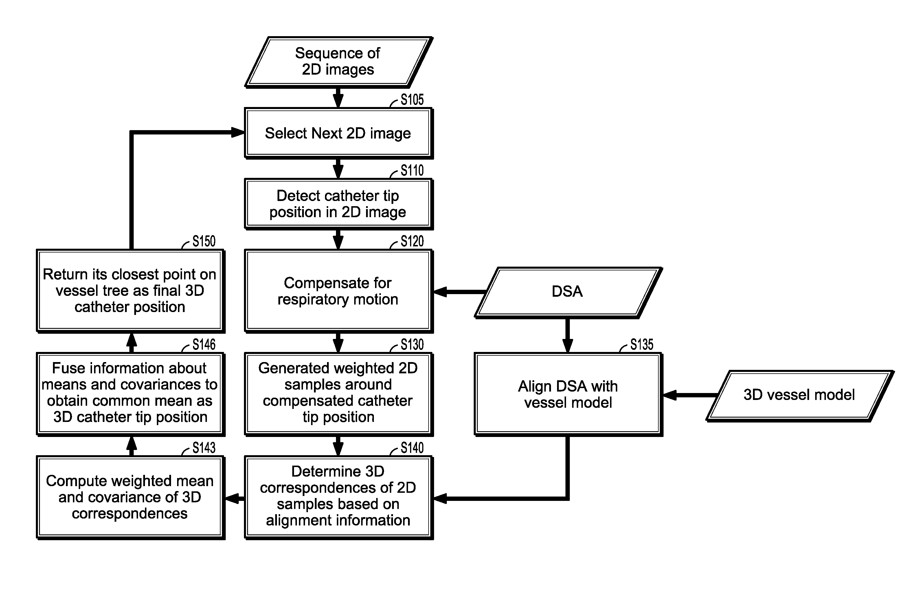
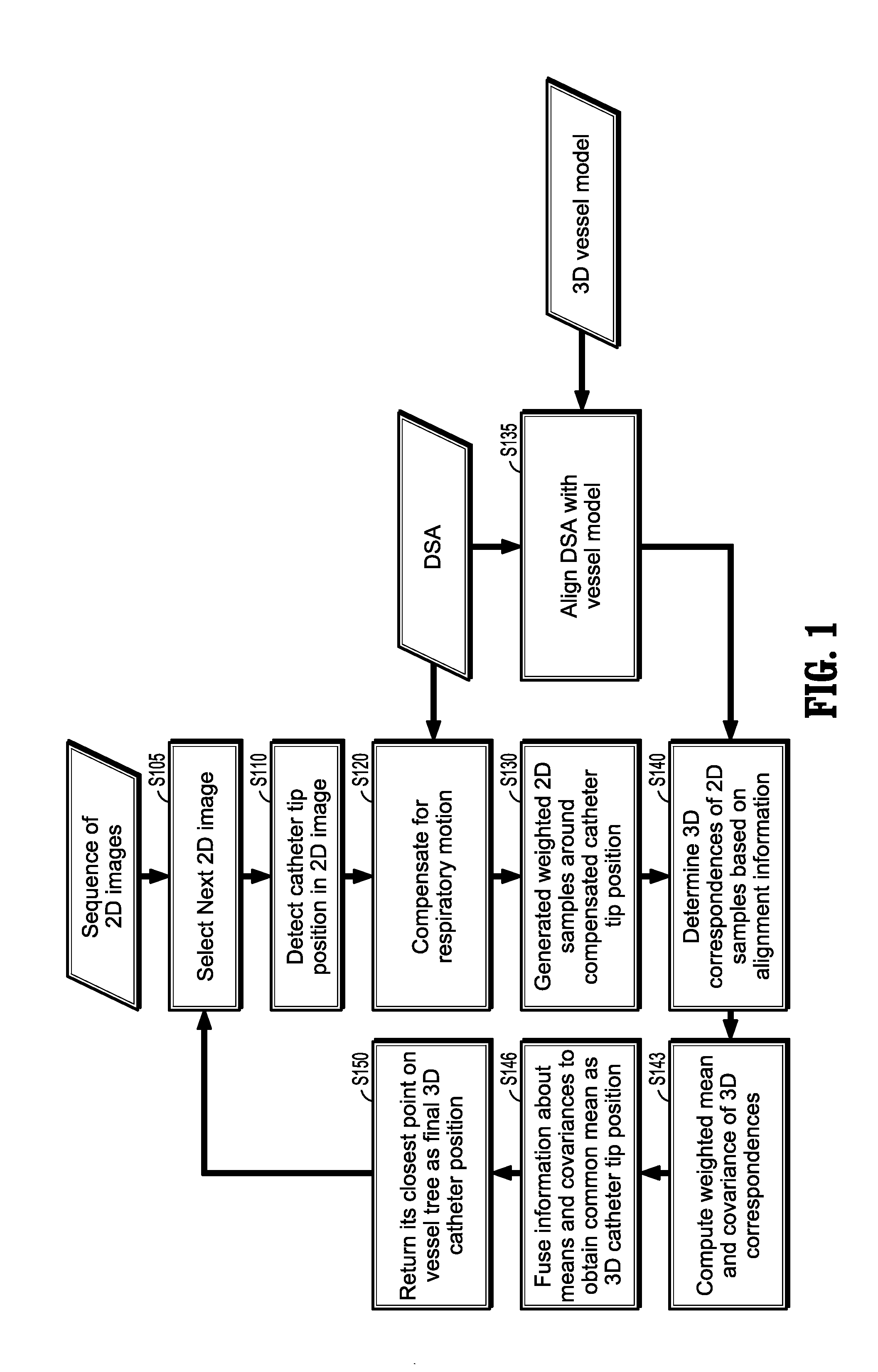
[0023]In general, exemplary embodiments for systems and methods determining the 3D position of a catheter tip will now be discussed in further detail with reference to FIGS. 1-3b. This invention may, however, be embodied in different forms and should not be construed as limited to the embodiments set forth herein. Rather, these embodiments are provided so that this disclosure will be thorough and complete, and will fully convey the scope of the invention to those skilled in the art.

[0024]It is to be understood that the systems and methods described herein may be implemented in various forms of hardware, software, firmware, special purpose processors, or a combination thereof. In particular, at least a portion of the present invention may be implemented as an application comprising program instructions that are tangibly embodied on one or more program storage devices (e.g., hard disk, magnetic floppy disk, RAM, ROM, CD ROM, etc.) and executable by any device or machine comprising sui...


PUM


Abstract

A method of determining a three-dimensional (3D) position of a catheter tip includes: compensating a 2D position of the tip of the catheter for respiratory motion to generate a compensated 2D catheter position, generating weighted sample points around the compensated 2D catheter position, determining correspondent points of the weighted sample points in a 3D image, computing a weighted mean and a weighted covariance of each correspondent point, and determining the 3D position of the catheter tip in the 3D image from a fusion of the weighted means and weighted covariances.

Description

CROSS-REFERENCE TO RELATED APPLICATIONS[0001]This application claims priority to U.S. Provisional Application No. 60 / 976,920, filed on Oct. 2, 2007, the disclosure of which is incorporated by reference herein.BACKGROUND OF THE INVENTION[0002]1. Technical Field[0003]The present disclosure relates to the dynamic road mapping of vascular system, and more particularly to methods for guiding a catheter through a dynamically mapped vessel.[0004]2. Discussion of Related Art[0005]Minimally invasive catheter-guided interventions play an important role in hospitals all over the world. A catheter is a medical device which may be introduced into a body channel or blood vessel for a variety of purposes. For example, one type is known as an intra-aortic balloon catheter which is used for cardiac assistance. Such catheters are frequently introduced into the body through the femoral artery because of the large diameter and accessibility of that artery. After insertion into the femoral artery, the d...

Claims


Application Information

Patent Timeline
Patent Type & Authority Patents(United States)
IPC IPC(8): A61B5/05
CPCA61B5/06A61B6/481A61B6/504G06T7/0044G06T7/0046A61B6/12G06T2207/10121G06T2207/30021G06T2207/30101G06T7/74G06T7/75A61B5/061A61B5/062
Inventor KHAMENE, ALIBENDER, FREDERIKWEIN, WOLFGANG
Owner SIEMENS HEALTHCARE GMBH
Why Eureka
Try Eureka