Eureka AIR delivers breakthrough ideas for toughest innovation challenges, trusted by R&D personnel around the world.

Leveling mechanism

Active Publication Date: 2012-10-02
DUST RSL LP
View PDF22 Cites 9 Cited by
  • Summary
  • Abstract
  • Description
  • Claims
  • Application Information

AI Technical Summary

Benefits of technology

[0014]To make easier the swiveling of the swivel pad on the base, it is anticipated that, when joined, the complimentary concave and convex surfaces define a space therebetween. Thus, the entire respective surface areas of the joined concave and convex surfaces may not be in contact thereby decreasing the amount of friction to be overcome when sliding the surface across one another. One approach for forming a space between the concave and convex surfaces is to provide a substantially flat portion or depression about the apex of the convex surface. This way, a space is formed between the joined concave and convex surfaces which decreases the amount of friction between them when the swivel pad is manipulated on the base since the amount of surface area in contact between the convex and concave surfaces is decreased. In an alternative approach, both the concave surface and the convex surface include a substantially flat portion or depression.
[0015]To connect a foot of a piece of equipment to the device, the base is equipped with a mounting stud anchored in the concave surface that extends upwards therefrom through an aperture in the convex surface of the swivel pad to connect with the foot. The aperture has a set diameter that is greater than the diameter of the stud to ensure that a predetermined amount of clearance exists between the wall of the aperture and the stud. This way, the swivel pad can be pivoted on the base while the stud is located through the aperture. Preferably, the diameter of the aperture relative to the diameter of the stud is sufficient to obtain 10° angularity between the top side of the swivel pad and the bottom side of the base.
[0017]By providing a hold down washer and nut according to the present invention, the base can be connected with mounting bolts and still maintain the ability to be adjusted horizontally across the mounting surface without being completely disengaged from the mounting bolts. Thus, each hold down washer includes an opening for receiving a mounting bolt, the opening having a diameter substantially equal to the diameter of the bolt, and a locking boss protruding from one side of the washer that is shaped to fit snuggly within the hole. During alignment operations, when it is desired to move the base while preventing disengagement with the mounting bolts, a hold down washer is placed over each mounting bolt with the mounting boss facing upwards. A nut is then tightened over the exposed end of each bolt so that the base cannot be disengaged from the mounting bolts by operation of the washers. Since the diameter of the bolts is less than the diameter of the respective holes in the base, the base can be horizontally adjusted in any direction, limited only by the amount of clearance between the bolts and the walls of the holes. Thus, each of the counter bored areas has a circumference or perimeter that is great enough to accommodate a washer without limiting the movement of the base about the mounting bolts. Another feature of the base is a detachable side-mounted jackscrew that enables slow, easy movement of the base from side to side during alignment.

Problems solved by technology

It is important that the centerline of the pump is perfectly aligned with the centerline of the driver, otherwise problems can arise including, for example, extreme heat and gear wear in the coupling, cracked or failed shafts from the constant flexing of the rotating shaft, overheating and fatigue problems, uneven face loading with stationary design mechanical seals and excessive axial movement of rotating design seals.
Although a coupling can compensate for axial growth of the shaft due to thrusting or thermal growth, its cannot compensate for radial misalignment between the pump and driver.
Laser aligning utilizes laser equipment which does an excellent job of making the measurements and calculating the amount of movement necessary, but one still has to move the hardware which is usually the most difficult part of alignment, in part, because of the lack of jack bolts on smaller pumps.
The task of aligning the centerlines of coupled hardware becomes more difficult when the surface on which hardware is to be mounted uneven.
Once a piece of equipment is mounted and aligned, over time the feet of the equipment can rust, leaving pits and irregularities in the feet.
Pitting and warping of the feet can lead to an unsatisfactory condition where the equipment becomes misaligned with a motor to which it is coupled.
Since it is typically too expensive or impractical to replace or resurface such feet, additional shims are usually installed to restore alignment of the equipment and motor.
As a result, the shim thickness between the various feet of the equipment can begin to vary greatly creating the potential for another misalignment situation called angular soft / foot.
This is a difficult problem to overcome since shims are designed only to take up space between two parallel surfaces.
However, this often results in an arrangement where very little surface contact exists between the foot and its mounting surface.

Method used


Image

  • Leveling mechanism
  • Leveling mechanism
  • Leveling mechanism

Examples


Embodiment Construction

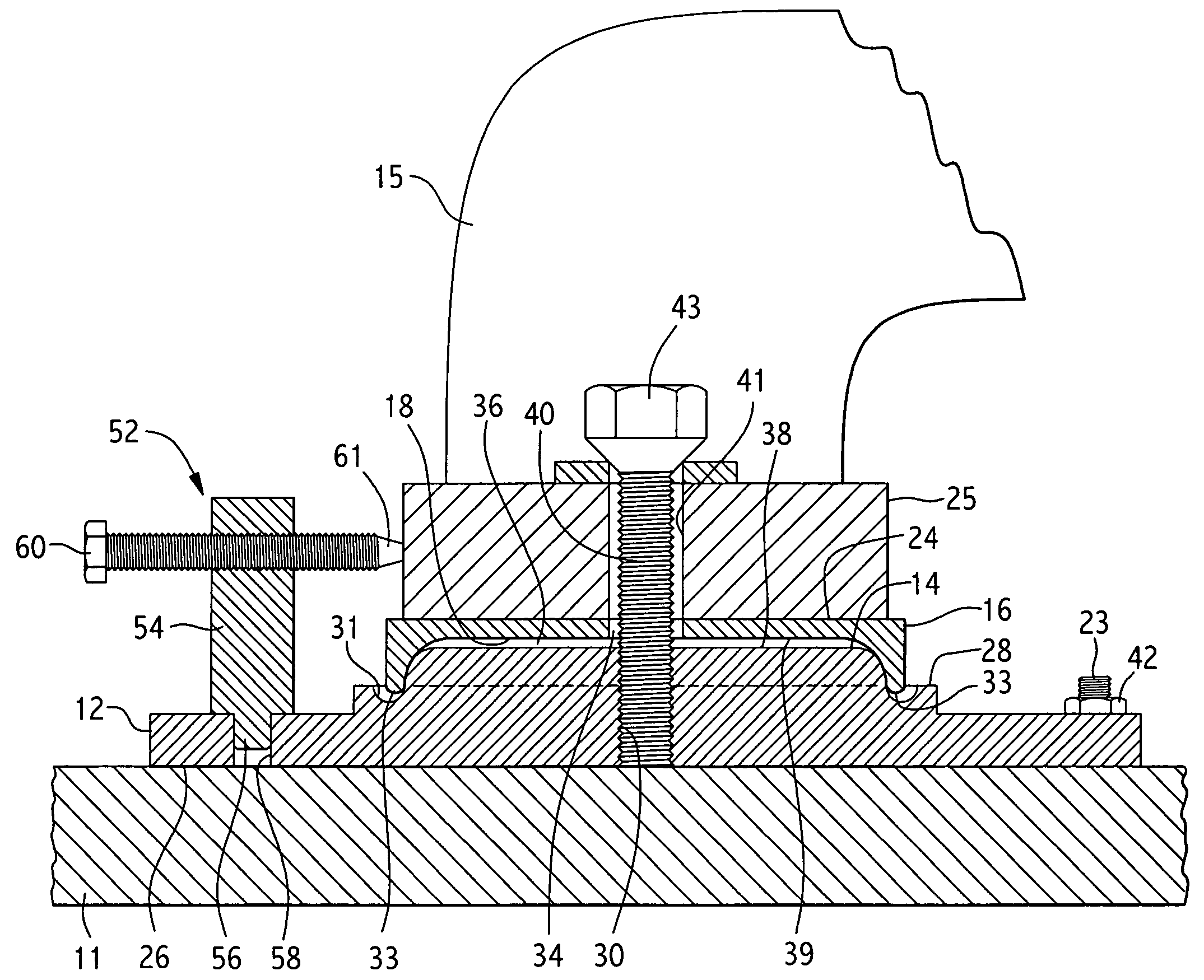
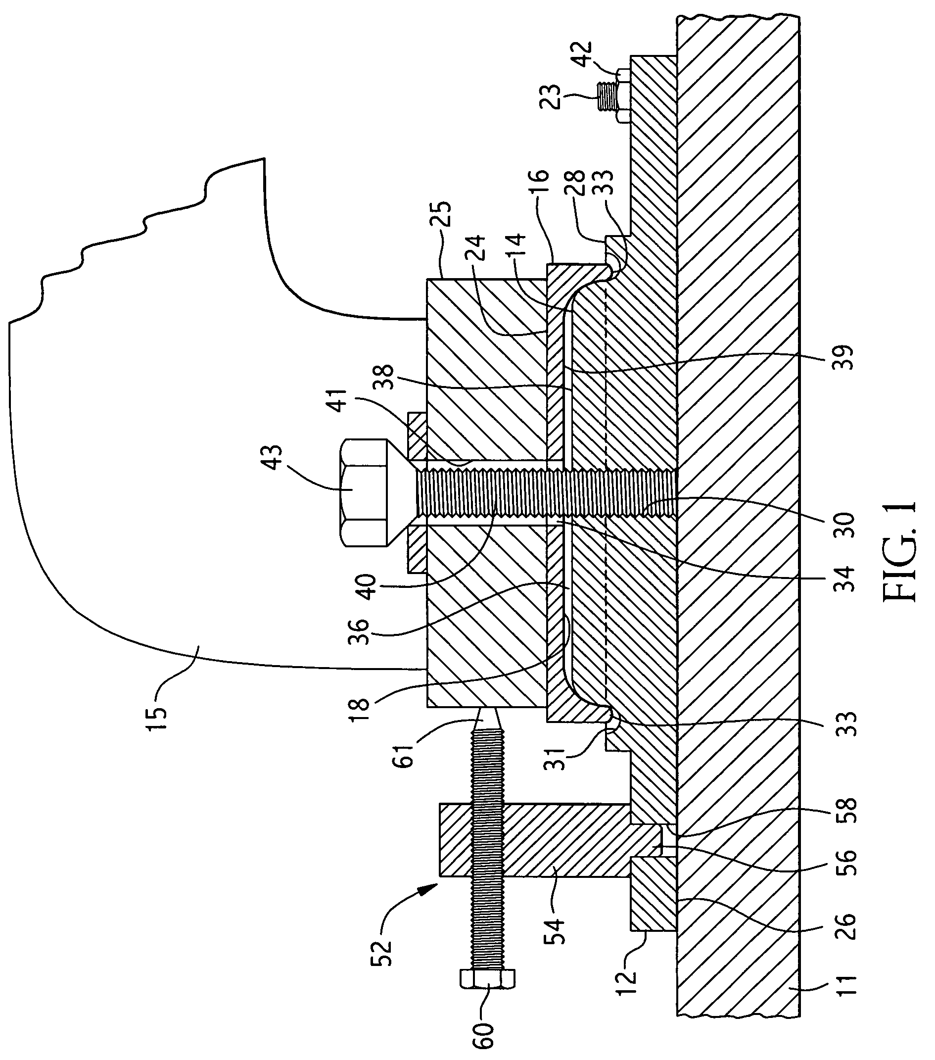
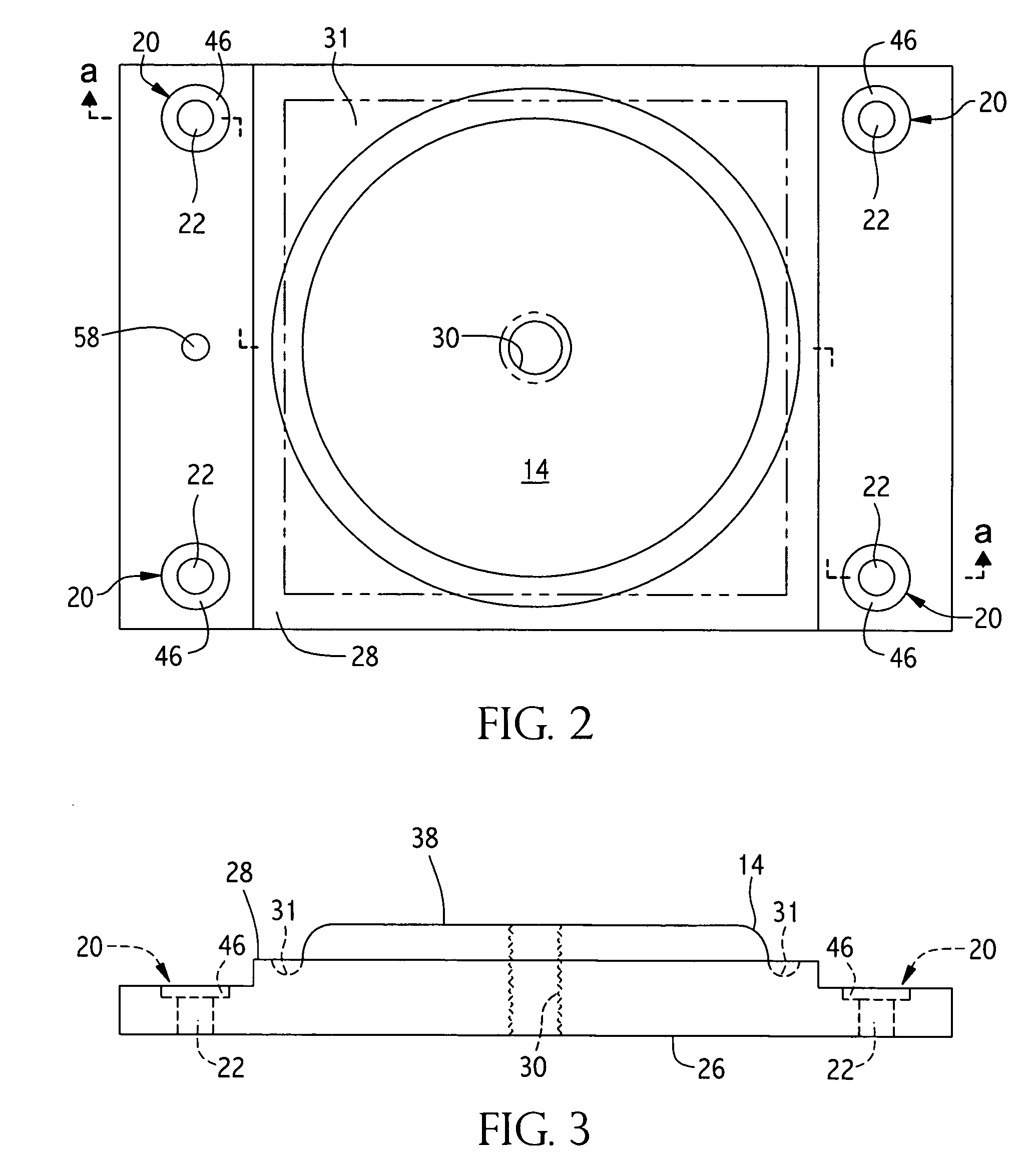
[0027]The preferred embodiment of the present invention is illustrated in FIGS. 1-8, where like portions share like numbering. Generally, as illustrated at FIG. 1, the equipment mounting and leveling device 10 of the present invention includes a base pad 12 for attaching device 10 to a mounting surface 11, base pad 12 including an upwardly facing circular convex portion 14, and a swivel pad 16 for selectively pivotally supporting a piece of equipment 15 on base pad 12. Swivel pad 16 includes a downwardly facing circular concave portion 18 that, when in use, is directed toward and selectively pivotally joined with convex portion 14. Mounting points 20 are provided around convex portion 14 on base pad 12 for connecting base pad 12 to a mounting surface 11. Each of mounting points 20 includes a mounting hole 22 through base pad 12 for receiving an anchor bolt 23 fixedly attached to mounting surface 11. Typically, four devices 10 and four sets of four anchor bolts 23 are required to mou...


PUM


Abstract

An equipment mounting and aligning device including a base having an upwardly facing convex portion and a swivel pad having a downwardly facing concave portion, the swivel pad being pivotally supported on the base by means of the complimentary concave and convex portions which, when joined, interact to allow the swivel pad to pivot to compensate for a piece of equipment's bent or irregular mounting feet and for uneven mounting surfaces.

Description

FIELD OF THE INVENTION[0001]The present invention relates to a leveling device and more particularly to a device for mounting and leveling heavy loads on a surface.BACKGROUND OF THE INVENTION[0002]Pumps and the like must be coupled to a driver component, usually an electric motor, in order to drive or turn the pump shaft. To do this, a coupling is connected between the pump and driver which transmits torque from the driver to the pump. It is important that the centerline of the pump is perfectly aligned with the centerline of the driver, otherwise problems can arise including, for example, extreme heat and gear wear in the coupling, cracked or failed shafts from the constant flexing of the rotating shaft, overheating and fatigue problems, uneven face loading with stationary design mechanical seals and excessive axial movement of rotating design seals. Although a coupling can compensate for axial growth of the shaft due to thrusting or thermal growth, its cannot compensate for radial...

Claims


Application Information

Patent Timeline
IPC IPC(8): F16M11/24F16M1/00
CPCF16M7/00F04D29/605
Inventor CADDELL, JOHN PHILLIP
Owner DUST RSL LP
Why Eureka
Eureka Blog
Learn More