High bandwidth power supply system with high efficiency and low distortion

a power supply system and high efficiency technology, applied in the direction of electric variable regulation, process and machine control, instruments, etc., can solve the problem of reducing the average distortion by limiting the frequency of switching correspondingly, and achieve the effect of low distortion, low distortion and high bandwidth operation

Active Publication Date: 2012-10-02
QUANTANCE
View PDF7 Cites 1 Cited by
  • Summary
  • Abstract
  • Description
  • Claims
  • Application Information

AI Technical Summary

Benefits of technology

[0008]Embodiments of the present invention include a power supply system using an improved Class G amplifier architecture to allow for high bandwidth operation with low distortion. The power supply system switches between multiple power supply rails, depending on the signal level handled by the power supply system. The lowest usable supply rail voltage is chosen to minimize power dissipation in the output driver, thus optimizing efficiency. Each supply rail has an associated driver capable of sourcing current to the amplifier output. When a supply rail is selected, the driver associated with the selected supply rail is enabled and other driver(s) not associated with the selected supply rail are disabled via separate disable control signals.
[0009]In one embodiment, the disabling of the deselected driver is delayed until current above a predetermined threshold is sensed at the output of the enabled driver. Thus, continuous current to the load of the power supply system is assured, and distortion is reduced.
[0010]In another embodiment, a timer is employed to limit the frequency of switching between the power rails. The timer is started when a supply rail is selected, and switching to a lower voltage supply rail is disallowed until the timer runs out. Since some distortion associated with the switching between power rails is unavoidable, limiting the frequency of switching correspondingly reduces the average distortion.
[0011]In still another embodiment, instead of a timer used to limit the frequency of switching between the power rails, the voltages of one or more power rails are adjusted. The power rails may be adjusted, so that the majority of the times the primary power rails are selected, and switching to the secondary rails occurs only occasionally. Thus, average distortion is reduced by the limited frequency of switching between the power rails.

Problems solved by technology

Since some distortion associated with the switching between power rails is unavoidable, limiting the frequency of switching correspondingly reduces the average distortion.

Method used


Image

  • High bandwidth power supply system with high efficiency and low distortion
  • High bandwidth power supply system with high efficiency and low distortion
  • High bandwidth power supply system with high efficiency and low distortion

Examples


first embodiment

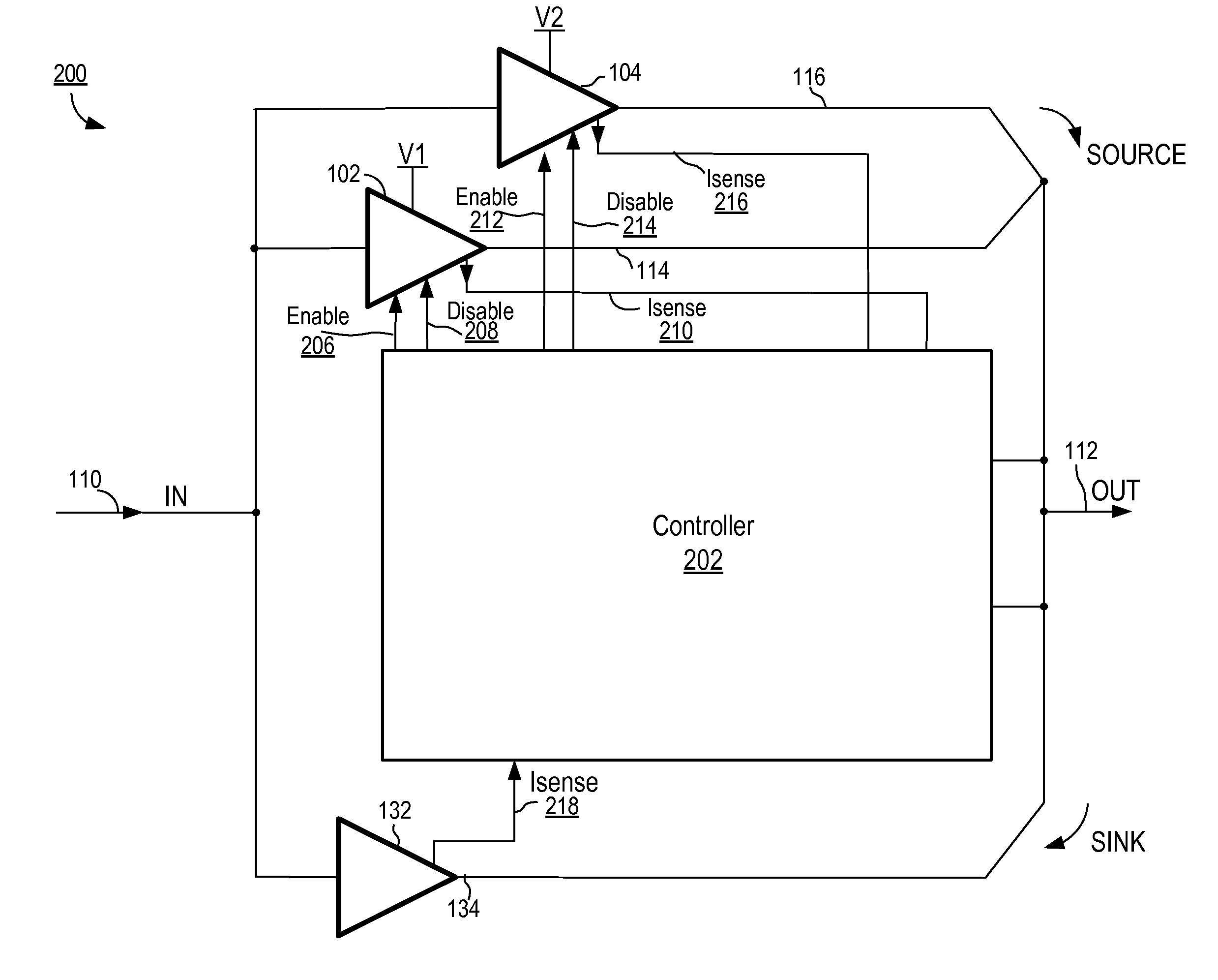
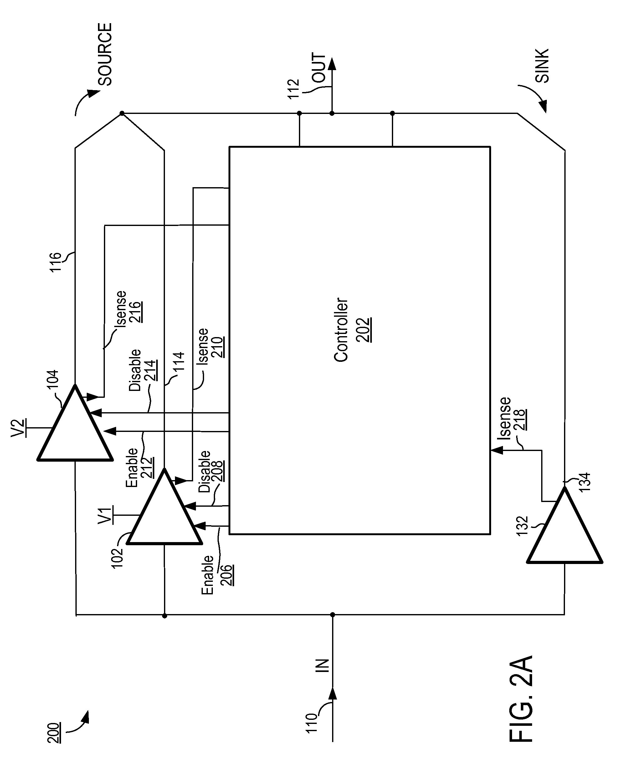
[0029]FIG. 2A illustrates a power supply system according to a The power supply system 200 of FIG. 2A uses a class G amplifier that is improved and modified to allow operation at higher frequencies while maintaining an acceptable level of distortion. Power supply system 200 includes source drivers 102, 104, a sink driver 132, and a controller 202. Power supply system 200 receives an input control signal 110 and generates a supply voltage output 112. Current sourcing drivers 102, 104 are associated with supply rails V1 and V2, respectively. Controller 202 includes the capability to independently enable current sourcing drivers 102 and 104 via enable signals 206, 212, respectively, and to independently disable current sourcing drivers 102 and 104 via disable signals 208, 214, respectively. The enable signals 206, 212 and disable signals 208, 214 may be edge triggered. As well, controller 202 senses current from the current source drivers 102, 104 via Isense signal lines 210, 216, res...

second embodiment

[0035]FIG. 2C illustrates a power supply system according to a The embodiment of FIG. 2C is substantially the same as the embodiment shown in FIG. 2B, except that timer 268 and switch 270 are added in the power supply system 250. Besides enabling source driver 104, the output 212 from comparator 244, when asserted, also resets timer 268 causing the timer 268 to count down from a predetermined timer period. While the timer 268 is counting, switch 270 is in the open position, preventing the enabling of source driver 102 until the timer 268 has timed out. Thus, the source driver 104 associated with the higher supply rail voltage V2 remains enabled during the predetermined timer period.

[0036]The purpose of this timer scheme is to further reduce distortion, by limiting the number of supply rail transitions, and thus limiting the frequency of the resulting “glitches.” The choice of the predetermined timer period in the timer 268 is made based upon a tradeoff between overall efficiency of...

third embodiment

[0040]FIG. 3A illustrates a power supply system according to a The power supply 300 of FIG. 3A is substantially similar to the power supply 200 of FIG. 2A, except that an adjustable power supply 306 provides the supply rail voltage V1308 for source driver 102 and controller 302 controls the supply rail voltage V1308 provided by adjustable power supply 306 via control signal 304 in a servo-control loop fashion. The supply rail voltage V1308 is adjusted so that this supply rail V1 and corresponding source driver 102 may serve as the primary supply rail for output 112 for most of the time, while still allowing occasional transitions to supply rail V2310 during peaks in the output voltage 112. A higher voltage at supply rail V1308 will typically result in fewer transitions to supply rail V2310, since the voltage at output 112 will more consistently remain below the voltage of V1308, thus reducing the frequency of need to switch to supply rail V2310. A system may be employed, such that ...


PUM


Abstract

A power supply system uses improved Class G amplifier architecture for high bandwidth operation with low distortion. The power supply system switches between multiple power supply rails, depending on the signal level handled by the power supply system. The lowest usable supply rail voltage is chosen to minimize power dissipation in the output driver, thus optimizing efficiency. Each supply rail has an associated driver capable of sourcing current to the amplifier output. When a supply rail is selected, its associated driver is enabled and other driver(s) not associated with the selected supply rail are disabled via separate disable control signals. The disabling of the deselected driver may be delayed until current above a predetermined threshold is sensed at the output of the enabled driver. In addition, the frequency of switching between the power rails may be limited via various means designed to limit distortion in the power supply system.

Description

BACKGROUND OF THE INVENTION[0001]1. Field of the Invention[0002]The present invention relates to a high bandwidth, high efficiency power supply system that can be used to power an RF PA (Radio Frequency Power Amplifier).[0003]2. Description of the Related Arts[0004]In certain electronic systems, there is a need for a high bandwidth, high efficiency power supply. As an illustrative example, a radio system may include an ET (envelope tracking) transmitter, where the RF PA is fed by a power supply which tracks the amplitude of the RF modulation. The RF PA is therefore supplied with a varying voltage that improves efficiency. Typically, the power supply providing power to such a PA is a linear regulator with a fast response, with the output voltage of the linear regulator controlled electronically to track the amplitude modulation. However, such a linear regulator is inefficient, as linear regulators control the output voltage via a dissipative pass transistor. A more efficient alternat...

Claims


Application Information

Patent Timeline
Patent Type & Authority Patents(United States)
IPC IPC(8): G05F5/00
CPCH03F1/0244H03F1/0277H03F1/32H03F3/24H03F2200/451H03F2200/507H03F2200/511H03F2200/555
Inventor JENSEN, BRENT ROGERDROGI, SERGE FRANCOISTOMASZ, MARTIN
Owner QUANTANCE
Why Eureka
Try Eureka