Fired heater for a hydrocarbon conversion process

a hydrocarbon conversion and heater technology, applied in steam boilers, multiple-effect evaporation, machines/engines, etc., can solve the problems of reducing the radiant efficiency of the heater, reducing the capital cost of the equipment and shutdown time, and reducing the potential for metal catalytic coking. , to achieve the effect of reducing the potential for metal catalytic coking, reducing the capital cost of equipment and shutdown time, and increasing the reliability of the subsequent reactor zon

Active Publication Date: 2012-10-09
UOP LLC
View PDF72 Cites 17 Cited by
  • Summary
  • Abstract
  • Description
  • Claims
  • Application Information

AI Technical Summary

Benefits of technology

[0022]The present invention can, with respect to conversion units such as reforming units, allow the economic design or expansion of an existing reforming unit by correcting maldistribution of fluid across the fired heater tubes in one or more fired heater cells using selectively placed restriction orifices. In an existing heater unit, such a modification may be done with minimal changes to the existing heater components, thereby reducing both the capital costs of equipment and shutdown time. Thus, the present invention can be particularly well-suited for revamping an existing heater suffering from maximum tube wall temperature limitations, which is generally below about 640° C. (1,184° F.), preferably no more than about 635° C. (1,175° F.). The lower resultant fired heater tube wall temperature(s) may also reduce the potential for metal catalyzed coking in the fired heater tubes, which can increase the reliability of the subsequent reactor zones and avoid some of the disadvantages associated with other coking solutions as discussed above. The present invention can also be used to intentionally create advantageous distribution of fluid across a set of fire heater tubes when for example, the fired heater has exhibited areas of increased or decrease heat input.

Problems solved by technology

However, these conventional designs suffer disadvantages.
Sometimes a conversion unit is limited by the heater if increasing the firing of the heater raises the temperature of the radiant and / or convection tubes to their maximum tube wall limit.
Moreover, generally there are three problems associated with operating a heater at or near the maximum temperature of the tube walls.
First, high tube wall temperatures increase the tendency of flue gas to oxidize on the sides of the tubes, leading to the formation of scale that decreases the radiant efficiency of the heater.
Second, high tube wall temperatures, particularly with respect to the first two reactors in a conversion process such as reforming, can cause cracking of the feed reducing yield.
Third, an additional complication is that reforming heaters are also susceptible to having metal-catalyzed coking in the fired heater tubes at higher temperatures.
Metal catalyzed coking can cause the shutdown of reforming units for maintenance work to remove the coke deposits in the reactors resulting from the onset of metal catalyzed coke formation in the fired heater tubes.
a) sulfur can be injected that inhibits coke formation, but this solution generally decreases reformer yields and may be unnecessary for some feeds that do not tend to coke;
b) the radiant tubes can be replaced with tubes of different alloys that can raise the maximum allowable heater tube wall temperature, but these alloys tend to be more expensive;
c) the heater can be enlarged with more tubes and / or burners to increase surface area, but enlarging a heater is usually expensive; and
d) a heater can be added to the series of heaters to provide some of the required duty, so the size of the existing heater can be decreased. However, adding a heater is also usually expensive.
Problems arise with maldistribution of the fluid across the heater tubes.
For example, the process outlet temperature of the heater overall is limited by the tube that rises to the highest tube wall temperature.
High fired heater tube wall temperatures can limit the potential feed rate increase or reformate octane increase for conversion units, such as reforming units.
Such tube wall temperature limitations can result in the installation of large expensive fired heater cells.
However, during refurbishment, many design variables are set, or changing the variables would lead to significant expense.
For example, manifold size and tube diameter are costly to change at the time of refurbishment.
Furthermore, analysis techniques of today may uncover problems that went previously undetected.
However, today's analyses show that is not necessarily true, especially in the case of refurbishments.
It has been discovered that the long held engineering assumptions were not always adequate and adjustments may need to be made to achieve uniform flow distribution across heater tubes.
Some adjustments, such as increasing the size of the manifold, may be quite costly.

Method used


Image

  • Fired heater for a hydrocarbon conversion process
  • Fired heater for a hydrocarbon conversion process
  • Fired heater for a hydrocarbon conversion process

Examples


Embodiment Construction

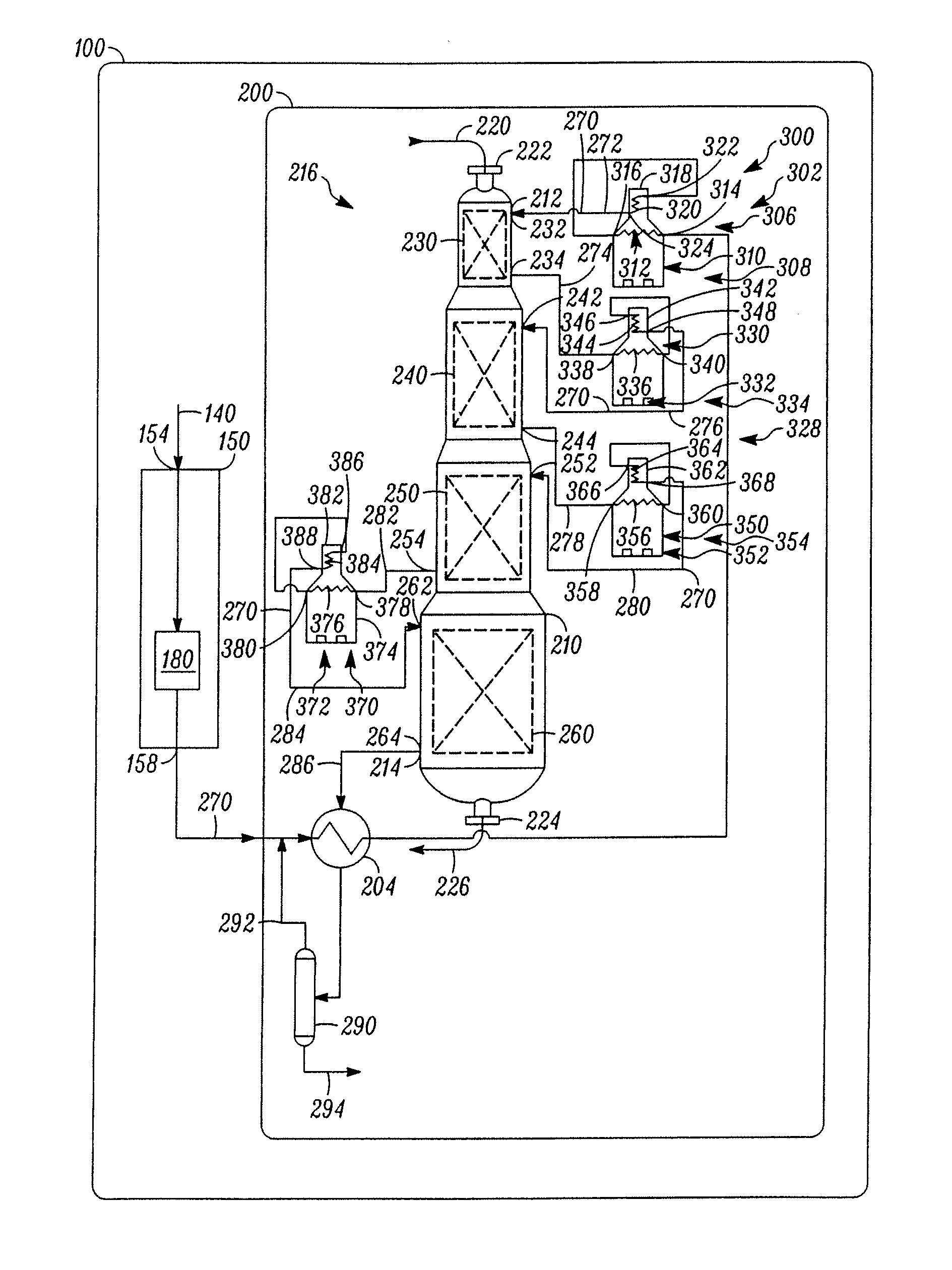
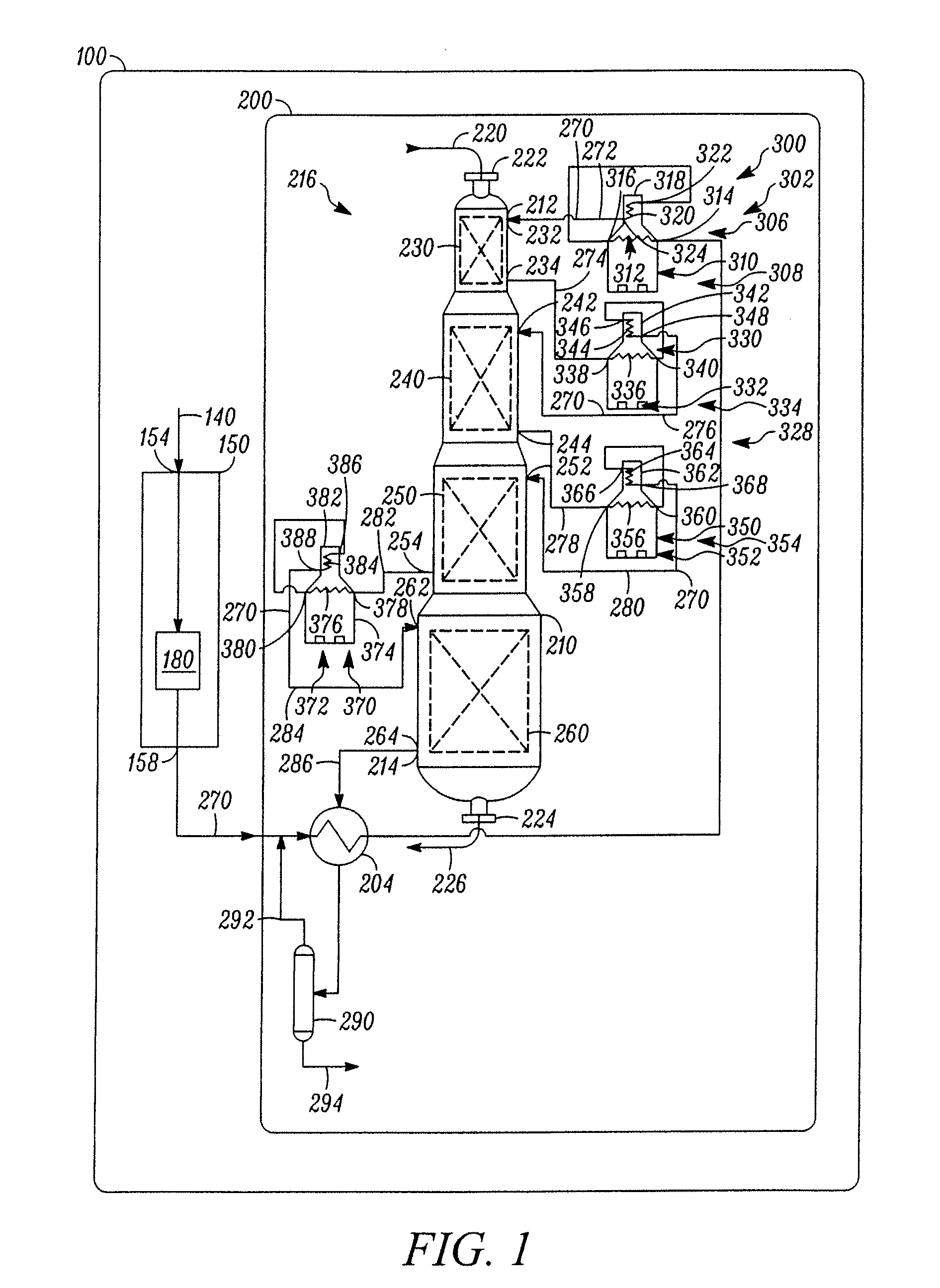
[0032]Generally, a catalytic conversion of a hydrocarbon-containing reactant stream in a reaction system has at least two reaction zones where the reactant stream flows serially through the reaction zones. Reaction systems having multiple zones generally take one of two forms: a side-by-side form or a stacked form. In the side-by-side form, multiple and separate reaction vessels, each that can include a reaction zone, may be placed along side each other. In the stacked form, one common reaction vessel can contain multiple and separate reaction zones that may be placed on top of each other. In both reaction systems, there can be intermediate heating or cooling between the reaction zones, depending on whether the reactions can be endothermic or exothermic.

[0033]Although the reaction zones can include any number of arrangements for hydrocarbon flow such as downflow, upflow, and crossflow, the most common reaction zone to which this invention is applied may be radial flow. A radial flow...


PUM

PropertyMeasurementUnit
temperatureaaaaaaaaaa
boiling pointaaaaaaaaaa
end boiling pointaaaaaaaaaa

Abstract

One exemplary embodiment of the present invention can be a fired heater for a hydrocarbon conversion process. The fired heater includes inlet and outlet headers or manifolds, a set of heater tubes with each heater tube having an inlet and an outlet, at least one restriction orifice adjacent the inlet of at least one heater tube. The restriction orifice may be within the inlet manifold and adjacent the inlet of a heater tube, or between the inlet manifold and the inlet to the heater tube. A process may include passing a hydrocarbon stream through the fired heater described herein during the course of operating a hydrocarbon conversion process.

Description

BACKGROUND OF THE INVENTION[0001]Hydrocarbon conversion processes often employ multiple reaction zones through which hydrocarbons pass in a series flow. Each reaction zone in the series often has a unique set of design requirements. A minimum design requirement of each reaction zone in the series is the hydraulic capacity to pass the desired throughput of hydrocarbons that pass through the series. An additional design requirement of each reaction zone is sufficient heating to perform a specified degree of hydrocarbon conversion.[0002]One well-known hydrocarbon conversion process can be catalytic reforming. Generally, catalytic reforming is a well-established hydrocarbon conversion process employed in the petroleum refining industry for improving the octane quality of hydrocarbon feedstocks, the primary product of reforming being a motor gasoline blending component or a source of aromatics for petrochemicals. Reforming may be defined as the total effect produced by dehydrogenation of...

Claims


Application Information

Patent Timeline
Patent Type & Authority Patents(United States)
IPC IPC(8): C10G69/02
CPCC10G9/00C10G29/205C10G35/02C10G45/02C10G45/58C10G45/68C10G47/00C10G49/002C10G59/02C10G69/08
Inventor PETERS, KENNETH D.
Owner UOP LLC
Why Eureka
Try Eureka