Diagnosis method for an exhaust gas post-treatment system

a technology of exhaust gas treatment and diagnostic method, which is applied in the direction of electrical control, exhaust treatment electric control, separation process, etc., can solve the problems of insufficient nox sensor sensitivity, inability to diagnose malfunction, and large volume reduction, so as to increase the exhaust counter pressure, reduce the air/fuel ratio, and increase the charge exchange work

Active Publication Date: 2012-10-16
AVL LIST GMBH
View PDF13 Cites 5 Cited by
  • Summary
  • Abstract
  • Description
  • Claims
  • Application Information

AI Technical Summary

Benefits of technology

[0030]During the diagnostic operating state or the sensor diagnostic operating state, NOx emissions are thus for a short time increased by a factor of roughly 2 to 10, as compared with the normal operating state, such that deficient reduction of nitrogen oxides can easily be detected even with NOx sensitive sensors of low sensitivity. Increased NOx emissions can be generated by diminishing the exhaust gas mass flow of recirculated exhaust gas, by reducing or at least partially bypassing the cooling of the exhaust gas mass flow cooled by an exhaust gas recirculation cooler, by increasing the boost pressure or by changing the injection timing or the injection pressure.
[0032]Diagnosis may be carried out during normal operation of the internal combustion engine. In order to avoid deterioration of driving comfort during the diagnostic process, it may be provided that during the diagnostic operating state or the sensor diagnostic operating state the torque of the internal combustion engine is kept equal to the torque of the normal operating state by increasing the amount of fuel injected.
[0040]It is of advantage if the variable throttle is located upstream of the exhaust gas treatment device. The throttle may be located downstream of the turbine of an exhaust turbo-charger.
[0041]To regenerate the exhaust gas treatment device the internal combustion engine switches to regeneration operation. In this mode the temperature behind the exhaust turbine must be increased, for instance to approximately 620° C., and a certain oxygen content in the exhaust gas, for instance 6%, must be maintained. The throttling device in the exhaust train will increase the exhaust counter pressure. This increases charge exchange work, with only a slight change in air mass flow. In order to maintain the torque the injected amount of fuel is increased, which leads to reduction of the air / fuel ratio and thus to a further temperature increase. Higher total mass flow as compared with throttling in the intake train, will substantially shorten the regeneration time of the exhaust gas treatment device. Furthermore, the influence on cylinder pressure is less pronounced than in the case of a throttle flap in the intake system, and thus switching will cause less change in engine noise.
[0042]The throttling device placed downstream of the turbine has the further advantage that the response of the internal combustion engine in transient operation is improved. In an acceleration process the throttle is opened, causing pressure at the turbine—and thus the power transmitted from the turbine to the compressor—to increase.
[0043]By raising the exhaust gas temperature this system will also accelerate warm-up of the internal combustion engine and thus improve the effectiveness of exhaust gas treatment devices, such as catalytic converters. A reduction of emissions over the driving cycle can thus be achieved.

Problems solved by technology

The sensitivity of commercially available NOx sensors is not sufficient, however, to perform the diagnosis task for all required engine operating points.
If conventional NOx sensors are used, it may happen that in spite of a malfunction of the SCR-system leading to increased NOx concentration in the exhaust gas behind the SCR-converter, even this increased concentration will be too low for detection by the sensor so that the malfunction cannot be diagnosed.
It is disadvantageous that throttling in front of the intake manifold will result in a considerable volume reduction, causing regeneration of the particulate filter to take longer.

Method used


Image

  • Diagnosis method for an exhaust gas post-treatment system
  • Diagnosis method for an exhaust gas post-treatment system
  • Diagnosis method for an exhaust gas post-treatment system

Examples


Embodiment Construction

[0050]Functionally equivalent parts are indicated by the same reference numbers in all variants.

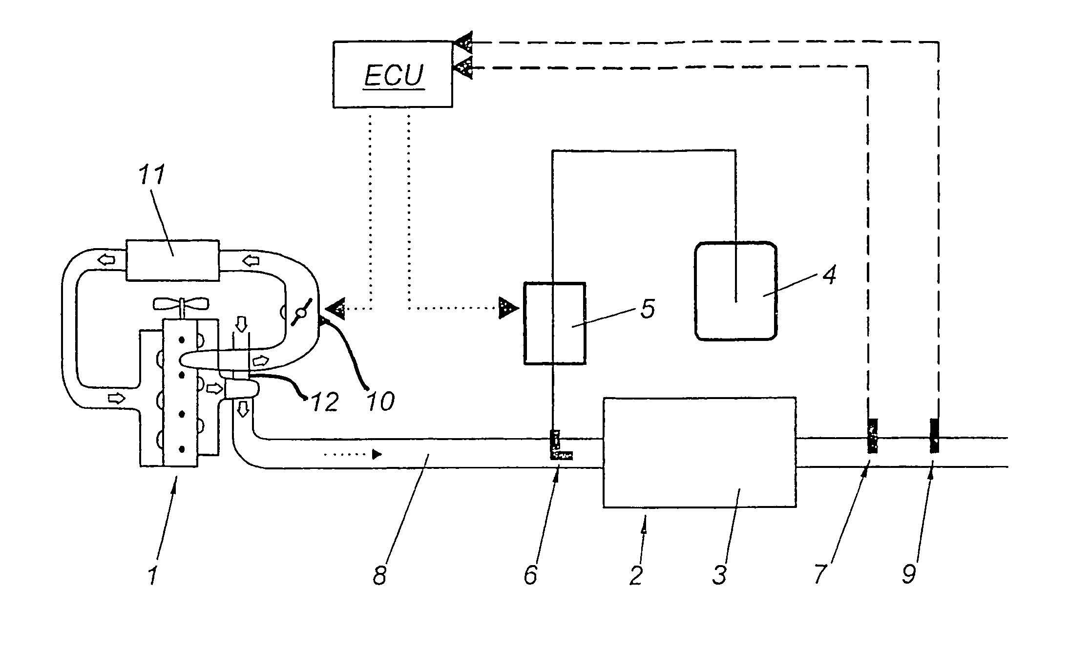
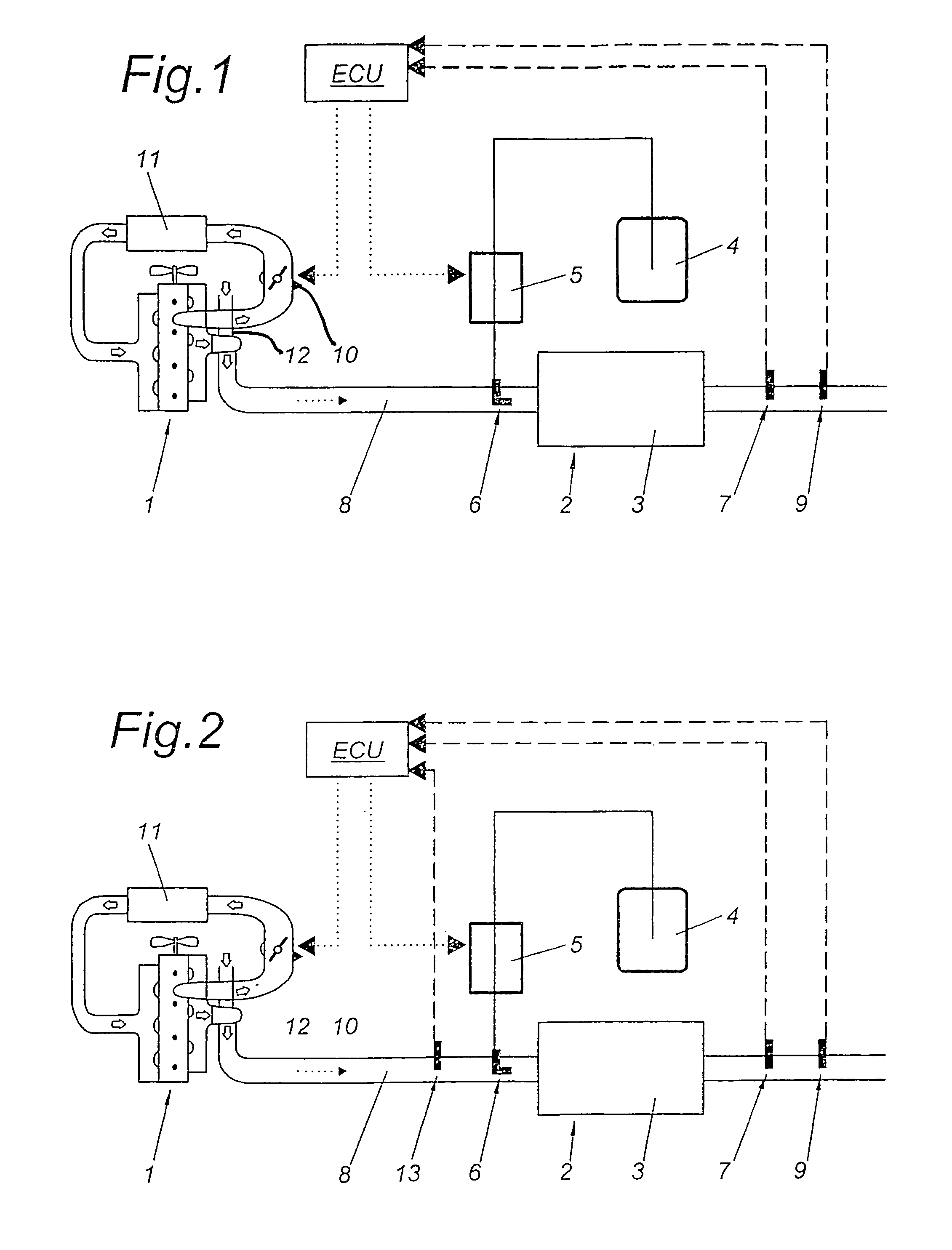
[0051]A first variant of the invention is shown in FIG. 1. The internal combustion engine 1 is equipped with an exhaust gas treatment device 2 consisting of an SCR catalytic converter 3, a tank 4 for a reducing agent, a metering device 5 for the reducing agent and an injection nozzle 6 for the reducing agent. The metering device 5 for the reducing agent is controlled by an electronic control unit ECU, which may be identical with the control unit of the internal combustion engine 1 or may be a separate control unit exchanging data with the control unit of the internal combustion engine 1. In the exhaust train there is located at least one temperature sensor 7 before or behind the SCR catalytic converter 3, which signals the temperature of the SCR catalytic converter 3 to the control unit ECU. A sensor 9 for measuring the concentration of nitrogen oxides (NOx) is also located in the exhaust...


PUM


Abstract

The invention relates to a diagnosis method for an exhaust gas post-treatment system for the reduction of nitric oxides in the exhaust gas train of an internal combustion engine by means of selective catalytic reduction. The following steps are provided for easy recognition of errors: definition of at least one threshold value for the Nox concentration for at least one engine operation point; shifting the operational mode of the internal combustion engine into an operational state of diagnosis, wherein in the operational state of diagnosis substantially more Nox emissions are produced than in the normal operational mode; determining an amount of reducing agents corresponding to the increased amount of Nox emisions in the operational state of diagnosis; controlling a dosing device in order to introduce the amount of reducing agents, corresponding to the increased amount of NOx emissions during the operational state of diagnosis, into the wase gas; measuring the concentration of NOx downstream from the post-treatment device; comparing the measured concentration of NOx to the threshold value; taking a decision as to the erroneous or error-free operation of the waste gas post-treatment system based on comparison of the measured concentration of NOx to the threshold value; terminating the operational state of diagnosis.

Description

BACKGROUND OF THE INVENTION[0001]1. Field of the Invention[0002]The invention relates to a method for diagnosing an exhaust gas treatment system for the reduction of nitrogen oxides in the exhaust gas train of an internal combustion engine by means of selective catalytic reduction, where a reducing agent is fed into the exhaust gas via a metering device, with at least one NOx-sensitive sensor located downstream of an exhaust gas treatment device, and further to a device for implementing the method. Furthermore, the invention relates to an internal combustion engine, in particular a diesel engine, with an exhaust train in which is located at least one exhaust gas treatment device, preferably a particulate filter, where regeneration of the exhaust gas treatment device may be initiated by increasing the exhaust gas temperature. The invention further relates to a method of operating an internal combustion engine.[0003]2. The Prior Art[0004]SCR-systems (Selective Catalytic Reduction) con...

Claims


Application Information

Patent Timeline
Patent Type & Authority Patents(United States)
IPC IPC(8): F01N3/00
CPCB01D53/9431B01D53/9495F01N3/023F01N3/0235F01N9/005F01N11/00F02B37/22F02D41/1463F01N3/2006F01N3/206F01N2260/14F01N2430/06F01N2430/08F01N2550/02F01N2560/026F01N2560/06F01N2570/14F01N2610/02F02B29/0406F02B37/00F02D41/0055F02D41/146F02M25/0707F02M25/0727Y02T10/144Y02T10/47F02M26/05F02M26/23Y02A50/20Y02T10/12Y02T10/40
Inventor ALLMER, INGOHUELSER, HOLGERHUSS, ARNO
Owner AVL LIST GMBH
Why Eureka
Try Eureka