Multistage vacuum pump unit and an operation method thereof

a vacuum pump and multi-stage technology, applied in machines/engines, liquid fuel engines, positive displacement liquid engines, etc., can solve the problems of inability to achieve power requirement reduction, excessive gas pressure in the gas flow passage of the succeeding stage vacuum pump, and increase the cost of facilities, so as to promote the cooling effect of branched gas, improve efficiency, and reduce the effect of fluctuation

Inactive Publication Date: 2012-10-16
ANEST IWATA CORP
View PDF6 Cites 3 Cited by
  • Summary
  • Abstract
  • Description
  • Claims
  • Application Information

AI Technical Summary

Benefits of technology

[0018]In the method of the present invention, while the multistage vacuum pump unit is under the low vacuum operation zone, a part of the gas is branched at a discharge side of a lower number stage vacuum-pump as well as on a upstream side of the next stage pump gas-inlet. Here, it is noted that the lower number stage vacuum-pump includes not only the first stage vacuum-pump but also other vacuum-pumps near to the gas-inlet side of the multistage vacuum pump unit; namely, the lower number stage vacuum-pump may be one of the second stage vacuum-pump, the third stage vacuum-pump and so on. The branched part of the discharged gas is led outside of a vacuum-pump unit casing of the multistage vacuum-pump unit, so that a power requirement for the vacuum-pump unit during the low vacuum operation can be reduced. So can be the vacuum-pump unit free from an excessive pressurizing of the next stage vacuum-pump on the gas flow passage after the part of the gas is branched; in addition, the necessary power to drive the vacuum-pumps can be reduced.
[0031]According to the present invention, in the method to operate a multistage vacuum pump unit, comprising a plurality of vacuum pumps that are connected in a series and in a multistage type, so that the space inside of a to-be-vacuumized container becomes under a medium or high vacuum condition; the method comprises the steps of branching a part of a gas discharged from a gas-outlet of a lower number stage vacuum pump while the unit is operated under a low vacuum condition; and discharging the branched gas, toward an air atmosphere, through a branch passage including a low conductance line on which at least one check valve is provided for preventing the branched gas from flowing back. Therefore, the power requirement in driving the vacuum pumps after they are started or while they are in a low operation zone can be reduced; further, even infinitesimal flow-back of the branched gas can be prevented. As a result, the operational efficiency of the vacuum pump unit cannot be worsened.

Problems solved by technology

In other words, according to the above manner, not only the above-described maximum power but also a starting power (such as an overshooting of a power requirement) are required when the vacuum pumps are started, for instance, in the case where the gas pressure in a to-be-vacuumized container is equal to a level of an atmospheric pressure; thus, a driving motor of a large power rating becomes necessary, and the cost of facilities is increased.
S62-48979 is straightly applied to the multistage vacuum pump as a structure thereof, and a highly compressed gas generated in a preceding stage vacuum pump is discharged into a subsequent stage vacuum pump, then the gas pressure in a gas flow passage of the succeeding stage vacuum pump becomes excessively high and a power requirement reduction can not be achieved.
On the contrary, high heat may be emitted in the subsequent stage vacuum pump.
Therefore, a pressure difference is developed between the outlet of the succeeding stage scroll pump and a place along the gas passage inside the vacuum pump in response to a produced high vacuum in a to-be-vacuumized container (a closed container as a load absorbing element); thus, there arises a risk that outside gas or air flows back inside of the vacuum pump, through the by-pass passage and the pressure control valve.
The potential back-flow causes a difficulty that an operational efficiency of the vacuum pump is lowered.

Method used


Image

  • Multistage vacuum pump unit and an operation method thereof
  • Multistage vacuum pump unit and an operation method thereof
  • Multistage vacuum pump unit and an operation method thereof

Examples


first embodiment

(First Embodiment)

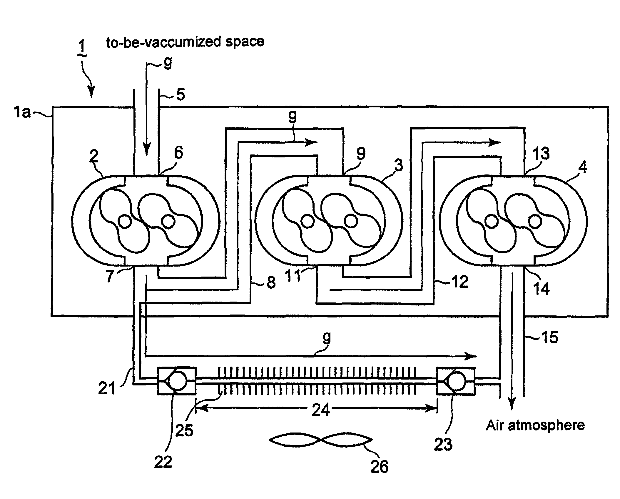
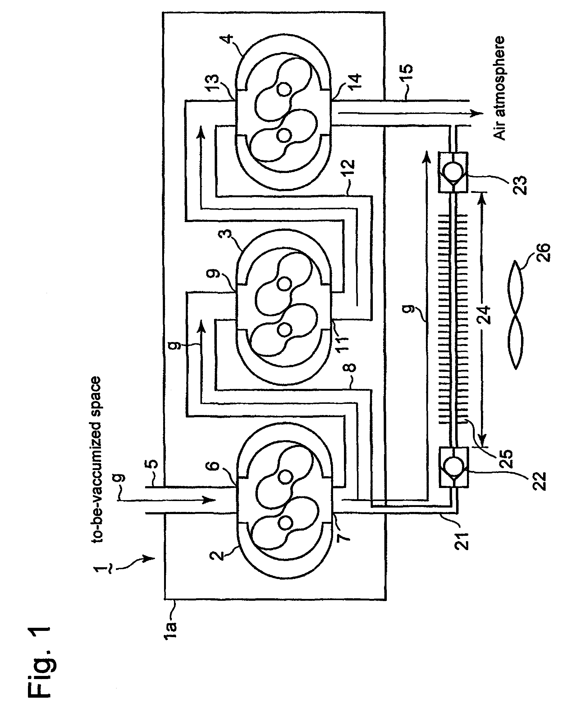
[0037]A first embodiment of the present invention here will be explained based on FIG. 1 which depicts a cross section of a multistage vacuum pump unit according to the first embodiment. In FIG. 1, the multistage vacuum pump unit 1 has a pump casing 1a in which three vacuum pumps 2, 3 and 4 are provided in series, forming a three stage pump unit; and gas passages communicating a gas-inlet of one pump with a gas-outlet of another pump. A suction passage 5 communicates the gas-inlet of the first stage vacuum pump 2 with a to-be-vacuumized container (not shown), namely, a closed container as a load-absorbing element.

[0038]A gas g inside the to-be-vacuumized container is inhaled into a first gas-inlet 6 of the first stage vacuum pump 2, through the suction passage 5; the gas g is compressed by the first stage vacuum pump 2, and the compressed gas g is discharged from a first gas-outlet 7 of the first stage vacuum pump 2, toward a first intermediate passage 8. The first...

second embodiment

(Second Embodiment)

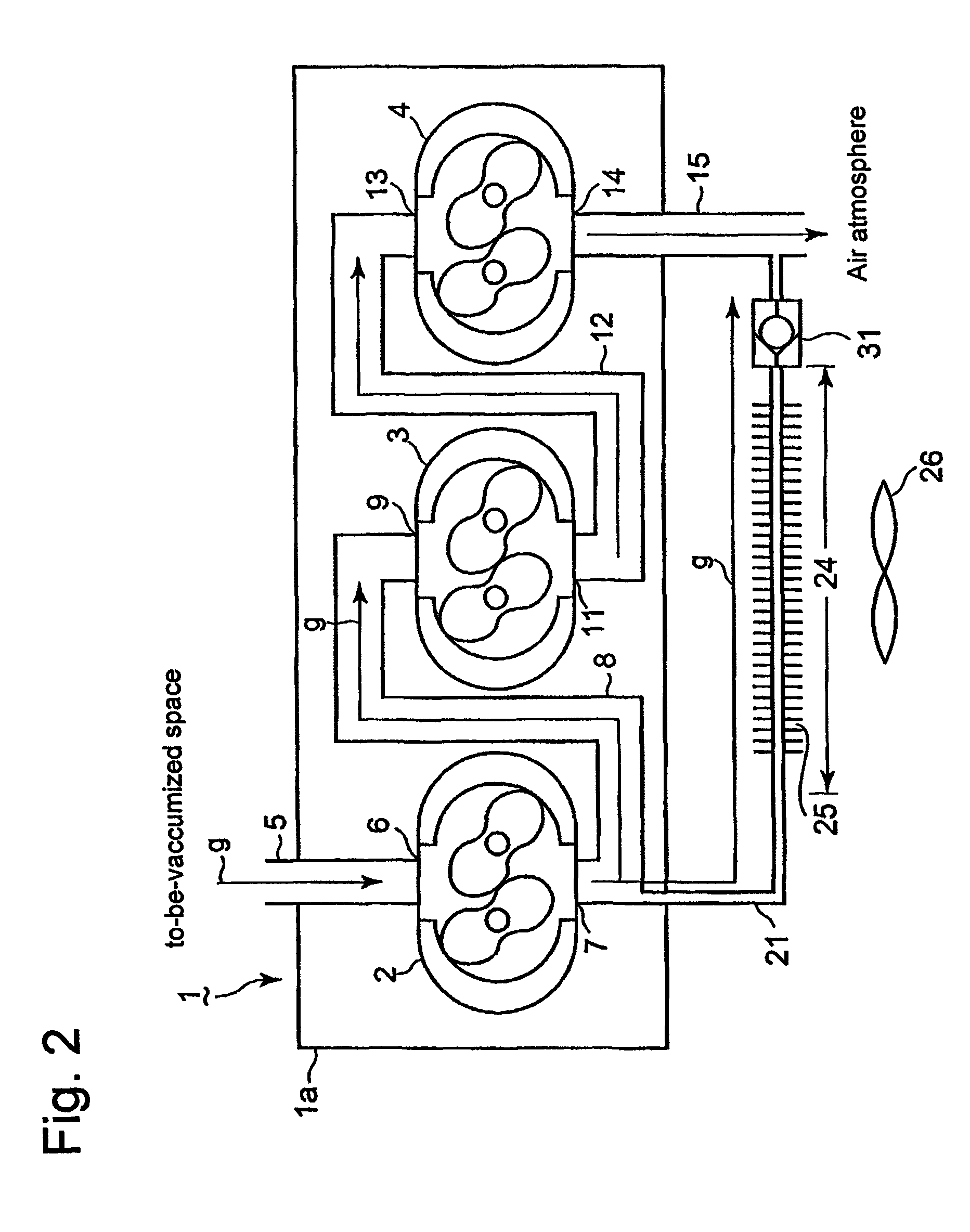
[0051]Next, a second embodiment of the present invention here will be explained based on FIG. 2 which depicts a cross section of a multistage vacuum pump unit according to the second embodiment. In the embodiment, only a check valve 31 is provided on a downstream side of the viscous flow line 24 that forms a part of the branch passage 21. In other words, the configuration of the second embodiment is the same as that of the first embodiment, except that the first check valve 22 in the first embodiment is deleted.

[0052]Also, by means of the configuration of the second embodiment, a gas flow-back from the discharge passage 15 toward the branch passage 21 can be well prevented; in addition, since only one check valve is provided on a part way of the branch passage 21, the cost of facilities can be reduced.

Industrial Applicability

[0053]The present invention enables a multistage vacuum pump unit to save a power requirement; at the same time, a gas discharged outside of ...


PUM


Abstract

A multistage vacuum pump unit can save a power requirement and prevent the gas discharged outside of the unit from flowing-back inside the pump unit. A plurality of vacuum pumps are connected in series to form the multistage vacuum pump unit. A suction inlet of a first stage vacuum pump thereof is connected to a to-be-vacuumized container so that the space inside of the container becomes under a high vacuum condition. In an operating method, part of the gas discharged into a first intermediate passage from the first stage vacuum pump is branched during a low vacuum operation, and discharged toward an air atmosphere through a low conductance line provided with check valves that prevent the branched gas from flowing back.

Description

BACKGROUND OF THE INVENTION[0001]1. Field of the Invention[0002]This application relates to a multistage vacuum pump unit and an operation method thereof, whereby energy-consumption-saving (a power requirement reduction) is achieved while the unit is started and an obtained vacuum state is under a low vacuum condition.[0003]2. Description of the Related Arts[0004]In conventional vacuum pumps, each pump requires maximum power of its own while the pump is started and an obtained vacuum state is under a low vacuum condition. As the gas pressure in a to-be-vacuumized container is lowered, power demand is gradually reduced. Thus, the power demand becomes minimal when an obtained vacuum pressure reaches a reference vacuum pressure, or an expected vacuum pressure.[0005]Some of the conventional vacuum pumps adopt a speed control for themselves when the obtained pressures become closer to ultimate (goal) pressures (high vacuum pressures), so that the above-described energy-consumption-saving...

Claims


Application Information

Patent Timeline
Patent Type & Authority Patents(United States)
IPC IPC(8): F04B23/04F04B23/00
CPCF04C28/26F04C23/001F04C18/126F04C2220/10
Inventor TANIGAWA, SHIRO
Owner ANEST IWATA CORP
Why Eureka
Try Eureka