Intrauterine deposit

a technology of intrauterine and deposit, which is applied in the field of intrauterine systems, can solve the problems of increasing bleeding of copper coil type iuds, complicated moulding procedures, and difficulty in ensuring correct dosage of agents,

Active Publication Date: 2012-10-23
MERCK SHARP & DOHME BV
View PDF12 Cites 6 Cited by
  • Summary
  • Abstract
  • Description
  • Claims
  • Application Information

AI Technical Summary

Benefits of technology

[0012]The present invention addresses these problems by providing an intrauterine system for the retention of a biologically active compound within the uterus of a female mammal, preferably a human. The system comprises a deposit of the compound, the deposit comprising a rate controlling structure that controls a rate of release of the compound within the uterus, a frame defining an interior space for receipt of the deposit, the frame having an open structure allowing access to a substantial part of an outer surface of the deposit and having one or more retention elements for retaining the frame within the uterus. Because of the open structure of the frame the greater part of the surface of the inserted deposit is directly exposed to the environment and hence the rate controlling effect on the steady state release of the compound to the uterus may be primarily determined by the structure of the deposit itself and the environment in which it is placed. This is extremely beneficial from a manufacturing perspective since once the frame is defined, existing drug formulations or controlled release capsules / fibers may be inserted into the frame. As release rates are primarily determined by the deposits themselves, release rates within the frame should be relatively easily predictable.
[0014]The invention further relates to an intrauterine system for the retention of a biologically active compound within the uterus of a female mammal, comprising a deposit of the compound in the form of a generally rod shaped element, a substantially flexible frame defining an interior space for receipt of the deposit and retention elements provided on the frame for retaining the frame within the uterus, wherein the flexible frame and the rod shaped element interact to form a composite structure having greater mechanical strength, in particular stiffness, than either the frame or the rod shaped element alone. Accordingly, an improved structure may be achieved that ensures adequate strength while still ensuring ease of insertion due to the small cross-section of the frame that may be achieved in this manner.
[0017]Preferably, the closure member comprises a plug. The plug may be integrally formed with the frame or may be a separate component. Although use of a plug or cap is preferred, the skilled man will understand that alternative closures may be used. In particular, the frame may be formed of two parts that join together around the deposit to contain it. Both parts may be connected to close the opening using mechanical means such as press fitting, form fitting, screw thread or the like. Alternatively, the parts may be glued, welded or otherwise bonded together. In a preferred embodiment, the plug is substantially impermeable and can cover and protect an end of the deposit as will be described below.
[0022]According to a further aspect of the invention, the deposit is substantially form stable and is not eroded during use. Due to the fact that the deposit is not eroded, there is little danger that it could exit from the open structure of the frame during prolonged retention in the uterus. In particular, the frame may be provided with large openings. Another attribute of a form stable deposit is that the mechanical integrity of the IUS remains intact due to interaction of the frame and deposit.
[0023]According to a still further aspect of the invention, the deposit may be manufactured in the form of a rod shaped element having a circumferential surface and two end surfaces. Preferred dimensions for the rod are 1.5-3.0 mm diameter and 20-45 mm in length for a single rod although under some circumstances diameters as low as 1.0 mm may provide sufficient release. In general, the dimensions may be largely dictated by standards bodies such as according to the above-mentioned ISO-7439.2002, which limits the overall length of an IUD to 36 mm. It will also be understood that different dimensions may be applicable e.g. if the deposit were to be located within an arm of an IUD device. Such deposits have been found convenient to manufacture by extrusion processes and may be subsequently cut into desired lengths for use. In particular, a deposit may be formed by a co-extrusion process to form a rod shaped polymer matrix surrounded by a release rate determining membrane. On cutting the extruded rod into lengths, the exposed ends are not covered by the membrane. In this case, it is desirable that the frame covers the two end surfaces to prevent or reduce release of compound from these regions in particular, the initial burst on commencing use. In this case in particular, it is the membrane around the circumferential outer surface of the deposit that is exposed by the open structure of the frame. To maximise the dosage retained in the deposit and / or to increase the strength of the system, the rod may extend substantially the whole length of the IUD.

Problems solved by technology

Copper coil type IUDs tend to increase bleeding during a woman's menstrual cycle.
Another difficulty encountered in manufacturing an IUS is the need to produce a structure that is strong enough to endure the forces of insertion, removal and usage without breaking yet again is small enough to prevent injury or pain on passing through the cervix.
On removal the arms must again fold without breaking off, since loss of part of the device within the uterus could lead to complications.
A further difficulty lies in ensuring correct dosage of the agent.
The need for integrity of the membrane has required complicated moulding procedures for connecting the body of the device to the agent deposit.
Any blockages of the perforations would affect the subsequent release of the medication.
The strength of the structure is provided by the external tube, which may make device insertion more difficult and painful.

Method used


Image

  • Intrauterine deposit
  • Intrauterine deposit
  • Intrauterine deposit

Examples


first embodiment

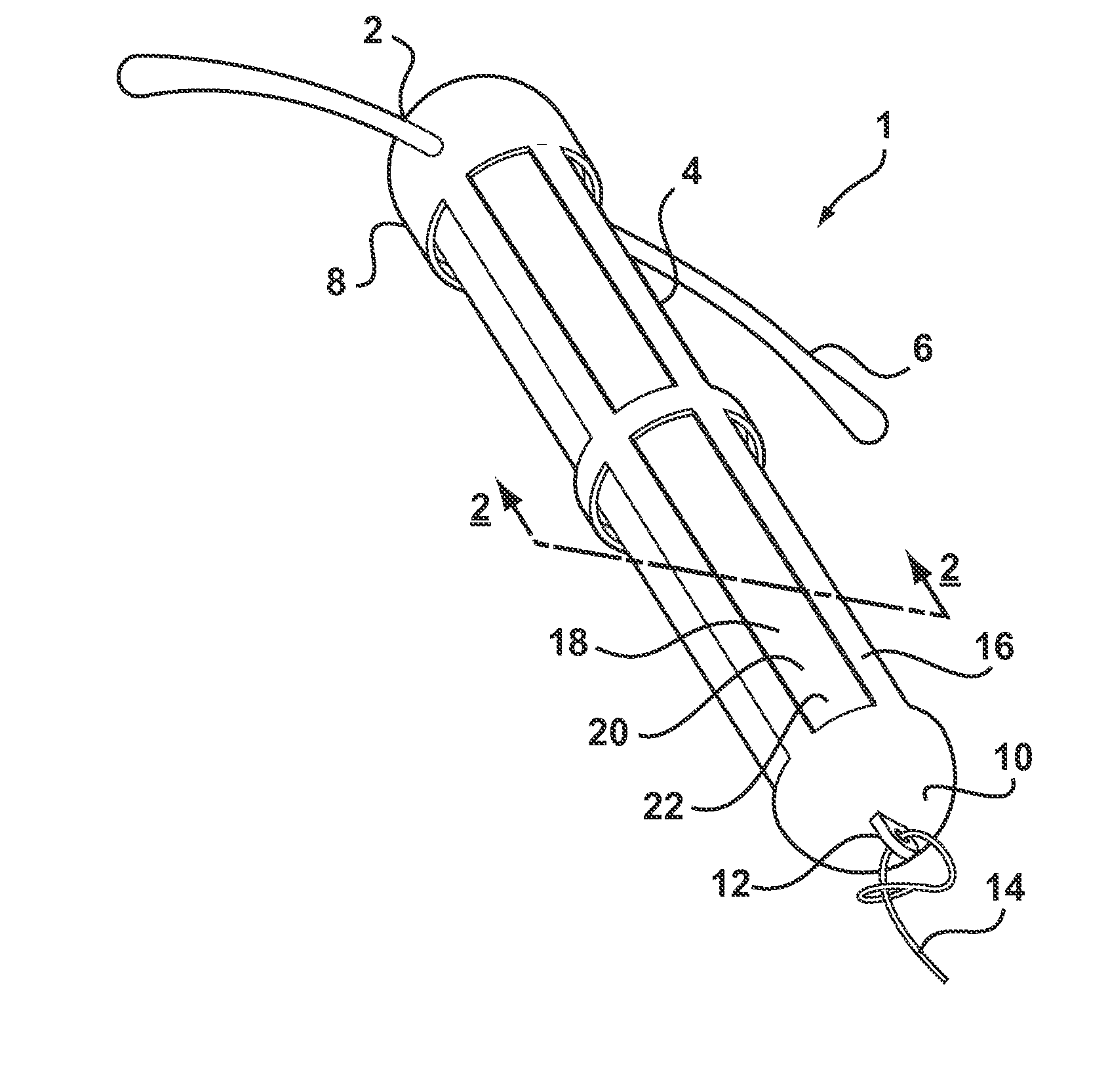
[0038]Referring to FIG. 1, there is shown an intrauterine system 1 according to the invention. The IUD 1 has a body 2 comprising a stem 4 with a pair of laterally extending arms 6 connected at its upper end 8. At a lower end 10 of the stem 4, there is provided an eye 12 to which is connected a nylon thread 14. The stem 4 is formed by a frame 16 having openings 18 to an interior space 20. Within the interior space 20 is located a rod shaped deposit 22.

[0039]FIG. 2 shows a cross-sectional view through the IUD 1 taken along line 2-2. FIG. 2 shows more clearly the frame 16 of the stem 4 and the deposit 22 received within the interior space 20. FIG. 2 also shows the deposit 22 to comprise a core 24 and an outer membrane 26. Core 24 is formed of a matrix consisting of EVA copolymer with a vinyl acetate percentage of 28%, to which a quantity of biologically active compound has been added. In the present embodiment, the core 24 is loaded with etonogestrel at 54 wt % with respect to other co...

second embodiment

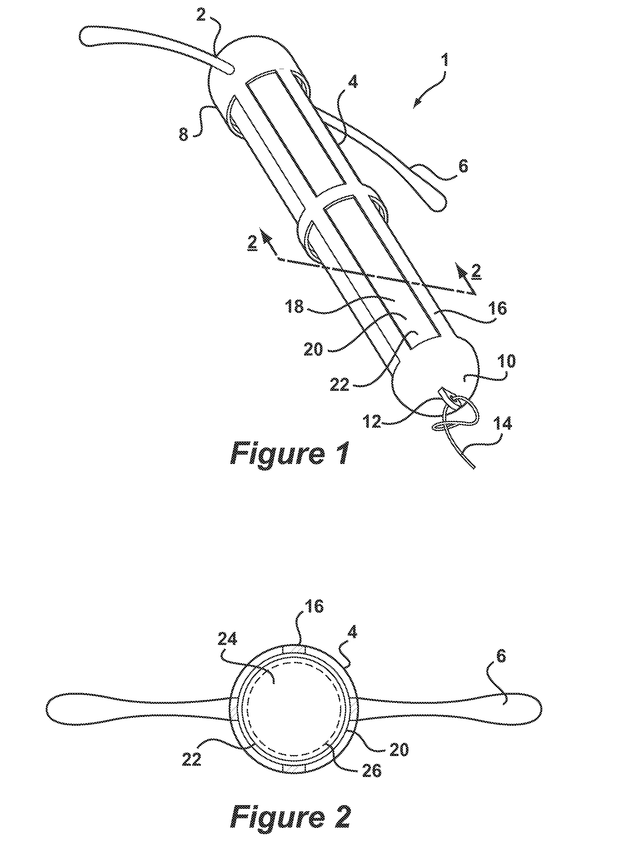
[0041]FIG. 3 depicts an IUD 100 according to the invention in which like reference numerals preceded by a 1 will be used to represent the same features as in the system of FIGS. 1 and 2. According to FIG. 3, IUD 100 comprises a body 102 having a stem 104. The stem 104 is formed by a helical coil 116 having openings 118 and an interior space 120. The coil 116 is preferably made of metal but could also be a moulded plastic component. Arms 106 are integrally formed with an upper end 108 of the stem 104 in which the coil 116 is embedded by a moulding procedure. A lower end 110 of the stem 104 is also formed as a moulding and provided with an eye 112 to which is connected thread 114. A deposit 122 is retained in the interior space 120. The deposit 122 may be generally identical to that of FIGS. 1 and 2. Insertion of the deposit 122 into interior space 120 takes place by deformation of the coil 116. Although the thread 114 is depicted as attaching to the lower end 110, it may also be desi...

third embodiment

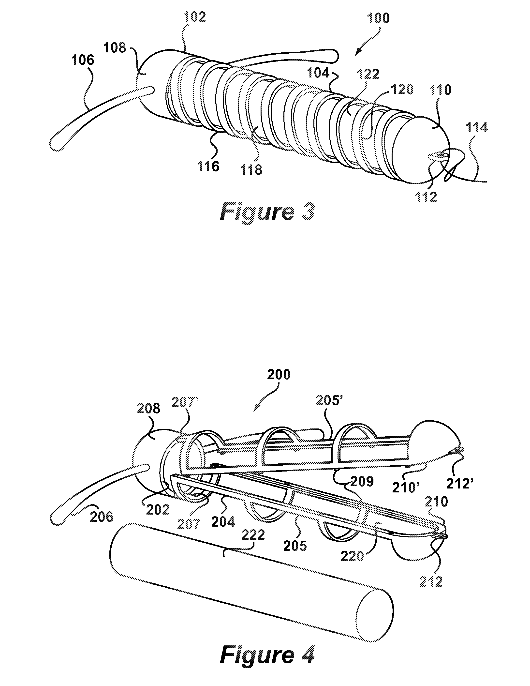
[0042]FIGS. 4 and 5 depict an IUD 200 according to the invention in which like reference numerals preceded by a 2 will be used to represent the same features as in the system of FIGS. 1 and 2. According to FIG. 4, the IUD 200 comprises a body 202 having a stem 204 formed in two frame halves 205, 205′ having snap elements 209. Eyes 212, 212′ are formed at lower ends 210, 210′ of frame halves 205, 205′. An upper end 208 of the stem 204 carries a pair of arms 206.

[0043]The body 202 is formed in an injection moulding procedure having living hinges 207, 207′ between the frame halves 205, 205′ and the upper end 208. After insertion of a deposit 222, the frame halves 205, 205′ are snapped together to form the stem 204 as shown in FIG. 5. The deposit 222 is now retained in interior space 220. Deposit 222 may be generally identical to that of FIGS. 1 and 2. Thread 214 is then passed through eyes 212, 212′ further restraining the frame halves 205, 205′ from opening.


PUM

PropertyMeasurementUnit
diameteraaaaaaaaaa
outer diameteraaaaaaaaaa
diameteraaaaaaaaaa

Abstract

An intrauterine system (1) for the retention of a biologically active compound within the uterus of a female mammal is formed by a frame (16) defining an interior space (20) for receipt of a deposit of the compound (22). The frame has an open structure (18) allowing access to a substantial part of an outer surface of the deposit and the deposit has a rate controlling structure that controls a rate of release of the compound within the Uterus. Retention elements (6) are provided on the frame for retaining the frame within the uterus.

Description

CROSS REFERENCE TO RELATED APPLICATION[0001]This application is entered into national stage examination under 37 U.S.C. 371 and stems from international patent application No. PCT / EP2008 / 065149 filed on Nov. 7, 2008.BACKGROUND OF THE INVENTION[0002]1. Field of the Invention[0003]The invention relates generally to intrauterine systems and in particular to devices that are capable of retaining and releasing a biologically active compound within the uterus. The invention further relates to a method of manufacturing an intrauterine system having a biologically active compound deposited therein.[0004]2. Description of the Related Art[0005]The use of intrauterine devices (IUDs) has long been recognised as a convenient manner of providing long-term contraception. The presence of a device within the uterus causes the release of leukocytes and prostaglandins by the endometrium or uterine lining. These substances are hostile to both sperm and eggs and are understood to prevent fertilization a...

Claims


Application Information

Patent Timeline
Patent Type & Authority Patents(United States)
IPC IPC(8): A61F6/06A61K9/22
CPCA61F6/14A61F6/144A61K9/0039A61F6/18Y10T29/4998A61F6/142Y10T29/49982A61P15/18
Inventor DE GRAAFF, WOUTERVEENSTRA, HARMMULDERS, TITIA MARTINE TRUCE
Owner MERCK SHARP & DOHME BV
Why Eureka
Try Eureka