System for controlling circulatory amount of particles in circulating fluidized bed furnace

a fluidized bed furnace and circulatory amount technology, applied in the direction of fluidised bed furnaces, fluid pressure control, apparatus for fluidised bed combustion, etc., can solve problems such as disadvantageous structure complexity

Active Publication Date: 2012-10-23
IHI CORP
View PDF11 Cites 12 Cited by
  • Summary
  • Abstract
  • Description
  • Claims
  • Application Information

AI Technical Summary

Benefits of technology

[0035]The fluidized bed gasification furnace comprises the first chamber for introduction of the raw material and the hot particles separated in the separator and the second chamber for supplying the particles introduced from the first chamber via the lower communicating portion below the partition means to the fluidized bed combustion furnace through overflow, the first pressure controller being provided to control the resultant gas induction means so as to keep the pressure in the first chamber to the preset pressure, the second pressure controller being provided to control the exhaust gas induction means so as to make difference in pressure between the first and second chambers equal to the preset differential pressure, the circulatory amount of the particles being controlled by adjusting in height the fluidized bed in the first chamber, so that obtainable is an excellent effect or advantage that, without changing the supplied amount of the gasification agent to the fluidized bed gasification furnace, the circulatory amount of the particles can be arbitrarily adjusted to arbitrarily enhance gasification efficiency in the fluidized bed gasification furnace.

Problems solved by technology

The flow rate controller 13, which has a movable portion required to moved within the communicating pipe 6a for control of the circulatory amount of the particles 3, requires countermeasure to high temperature and therefore is disadvantageously complicated in structure.

Method used


Image

  • System for controlling circulatory amount of particles in circulating fluidized bed furnace
  • System for controlling circulatory amount of particles in circulating fluidized bed furnace
  • System for controlling circulatory amount of particles in circulating fluidized bed furnace

Examples


Embodiment Construction

[0080]Embodiments of the invention will be described in conjunction with attached drawings.

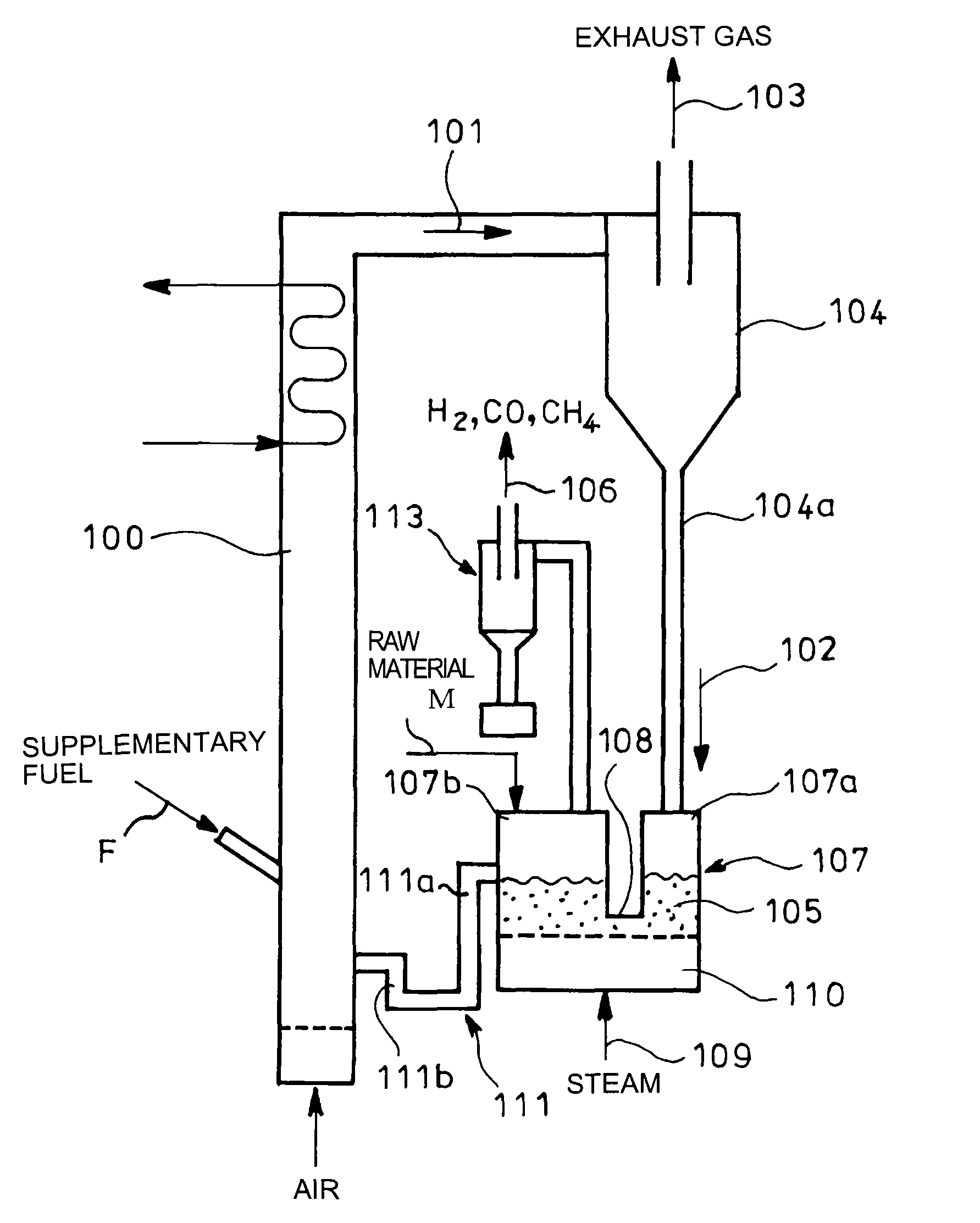
[0081]FIG. 4 shows an embodiment of the invention which is similar in fundamental construction to FIG. 3. Parts identical with those in FIG. 3 are denoted by the same reference numerals and explanations therefor are omitted; only characteristic portions of the invention will be described in detail.

[0082]A fluidized bed gasification furnace 107 shown in FIG. 4 has a gasification agent box 110 arranged below the furnace for introduction of a gasification agent 109 such as steam, air or carbon dioxide. An inside of the fluidized bed gasification furnace 107 is partitioned into first and second chambers 113 and 114 by partition means in the form of a partition wall 112 extending from above into a fluidized bed 105, the first and second chambers 113 and 114 having high- and low-volume, respectively. Formed between a lower end of the partition wall 112 and the gasification agent box 110 is a lower c...


PUM


Abstract

The invention has its object to arbitrarily adjust an amount of particles to be circulated without changing a flow rate of a gasification agent to thereby enhance gasification efficiency in a fluidized bed gasification furnace.The fluidized bed gasification furnace 107 comprises first and second chambers 113 and 114 in communication with each other in a fluidized bed 105. The hot particles 102 separated in the separator 104 and raw material M are introduced into the first chamber 113. The particles 102 introduced from the first chamber 113 through interior in the fluidized bed 105 to the second chamber 114 are supplied in an overflow manner to the fluidized bed combustion furnace 100. A first pressure controller 121 is provided to control the resultant gas induction means 116 such that the pressure in the first chamber 113 is kept to preset pressure 120; and a second pressure controller 124 is provided to control the exhaust gas induction means 118 such that difference between pressure in the first and second chambers 113 and 114 is equal to the preset differential pressure 123, so that the fluidized bed 105 in the first chamber 113 is controlled in height to control an amount of particles 102 to be circulated.

Description

TECHNICAL FIELD[0001]The present invention relates to an system for controlling a circulatory amount of particles in a circulating fluidized bed furnace wherein particles are circulated between a fluidized bed combustion furnace for heating of the particles and a fluidized bed gasification furnace for gasification of raw material through heating of the raw material by the heated hot particles.BACKGROUND ART[0002]Conventionally known are circulating fluidized bed boilers as shown in References 1 and 2, JP 2005-274015A and JP 2004-132621A, respectively. FIG. 1 shows a circulating fluidized bed boiler of Reference 1 comprising a fluidized bed combustion furnace 1 for heating of particles (sand) through fluidized combustion by supply of fuel A into a fluidized bed of the particles fluidized through blowing-in of air, a separator 5 in the form of a cyclone for introduction of burnt gas 2 from a top of the furnace 1 and separation of the burnt gas into hot particles 3 and exhaust gas 4, a...

Claims


Application Information

Patent Timeline
Patent Type & Authority Patents(United States)
IPC IPC(8): B01J19/00B01J8/18
CPCC10J3/482C10J3/56C10J3/62C10J3/723F27B15/18F23C10/10F23C10/32C10J2300/093C10J2300/0973C10J2300/1637C10J2300/1807C10J2300/1853F23C2206/102C10J2300/1606
Inventor SUDA, TOSHIYUKIMATSUZAWA, YOSHIAKIFUJIMORI, TOSHIRO
Owner IHI CORP
Why Eureka
Try Eureka