Image transforming device

a technology of transforming device and image, which is applied in the field of optical systems, can solve the problems of difficult installation setup, difficult to find the right position, and undesirable three-dimensional (3d) image, and achieve the effects of low cost, high resolution and convenient manufacturing in large-series

Inactive Publication Date: 2012-10-23
VAN NULAND HENRICUS SERVATIUS FRANSISCUS
View PDF46 Cites 7 Cited by
  • Summary
  • Abstract
  • Description
  • Claims
  • Application Information

AI Technical Summary

Benefits of technology

[0025]The image transforming device is a compact apparatus that rearranges pixels received from a projected two-dimensional image to deliver an output image that has high resolution in a different format than the resolution of the input image.
[0026]The image transforming device is amenable to manufacturing in large series at a very low cost, preferably less than about $100 so as to enable it to be used in commercially viable auto-stereoscopic displays.
[0027]The image transforming device produces an image at a light emitting screen with full color pixels where there are more pixels horizontal than vertical as compared with the original two-dimensional image. And in that way, a 3D image can be created in a much more suitable format / resolution. This is accomplished using ribbons of optical waveguides having a defined placement so as to create an auto-stereoscopic image with many viewing zones. The image transforming device is preferably used for auto-stereoscopic displays or 3D imaging and an array of such devices can form a bigger screen. The image transforming device can be made so that the screen can be curved to create cylindrical displays.
[0028]Glassfibers preferably used as optical waveguides in ribbon form are very cheap basic material. For one device the fiber would cost $20. Then, that fiber would be processed by a winding, cutting, stacking robot, preferably in a manufacturing operation at 24 hours per day, 7 days a week, which would yield a final cost of manufacturing will be about $35.
[0029]Embossing / etching plastic ribbons would be even more economical because the material cost will be less than $20 and the winding process is not necessary. Using a roll of ribbons enables simply cutting the correct length and stacking, which makes the manufacturing cost about $25 and increases the production speed by a factor.
[0030]The proposed solution is significantly better than current technology because there is no need to create a perfect grid of fibers on the receiving end; and that makes it possible to have a high-speed manufacturing. So commercially attractive products can be made using glassfiber, or embossed transparent plastic, as optical waveguides. Using a dynamic micro-lens array makes it possible to use a lower resolution image and still be able to get all the views needed for high-resolution 3D images. Using a lower resolution image and the associated electronics would be less expensive. Alternatively, using the dynamic micro-lens array with a high resolution image would increase the number of viewing zones and the 3D image quality by a factor, which is not realistically obtainable when using one pixel per fiber image guiding devices.

Problems solved by technology

This low number makes it difficult to find the right position, and stay in the position, to be able to see the stereo image.
The number of available pixels and their relative large size make creating more viewing zones result in an undesirable low resolution three-dimensional (3D) image.
Such an installation is difficult to setup and there are many details such as optical distortions to take care of in order to obtain a good-quality 3D image.
These optical fiber tapers are rigid, difficult to produce in larger sizes (maximum 20 centimeters), have a limited, 1:6, ratio between input and output surface and are not flexible limiting its use to create large displays cost effectively.
This is done by using relatively thick optical fibers resulting in a not-always-compact end-screen with an enlarged image less suitable to create auto-stereoscopic displays.

Method used


Image

  • Image transforming device
  • Image transforming device
  • Image transforming device

Examples


example 1

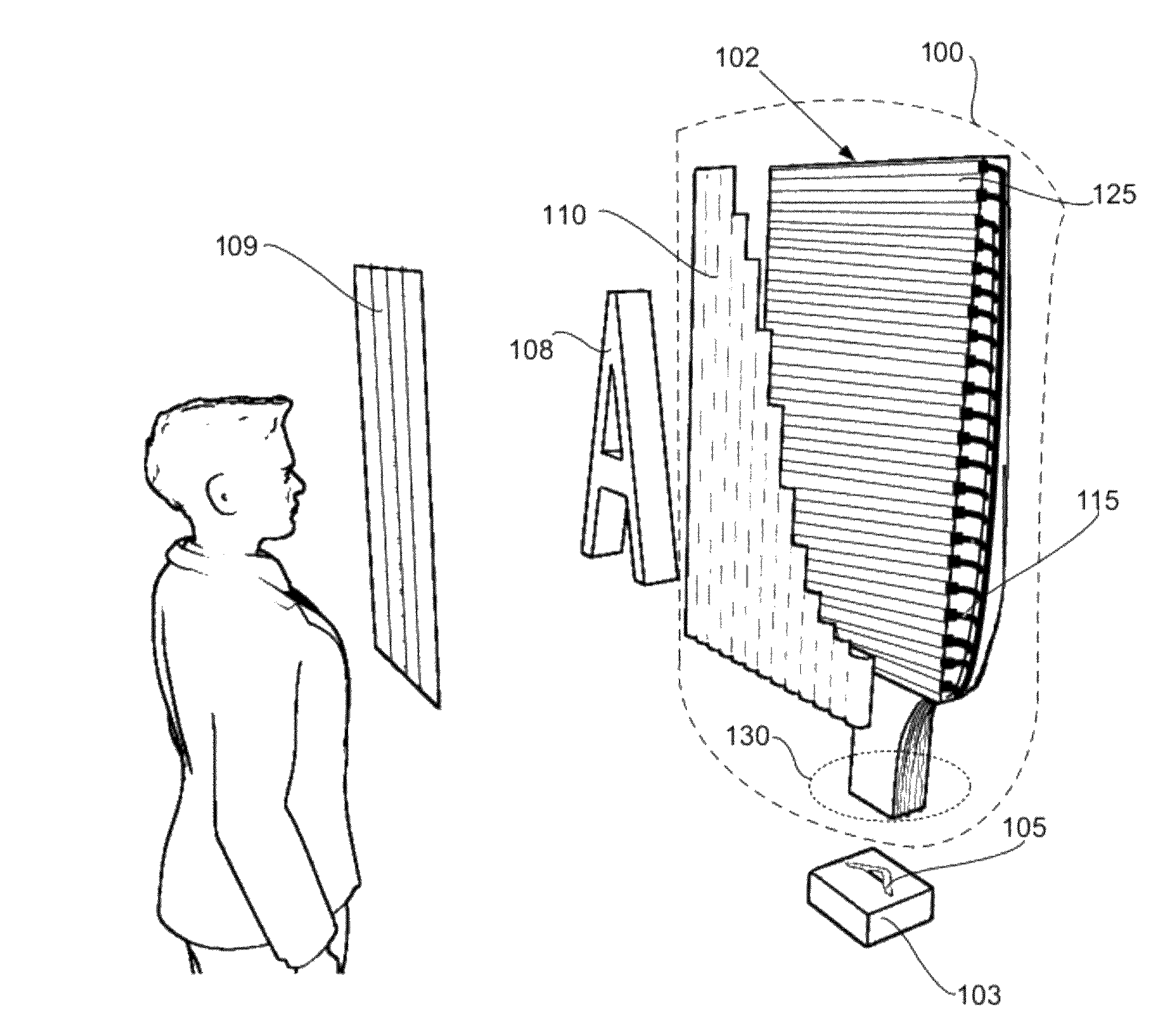
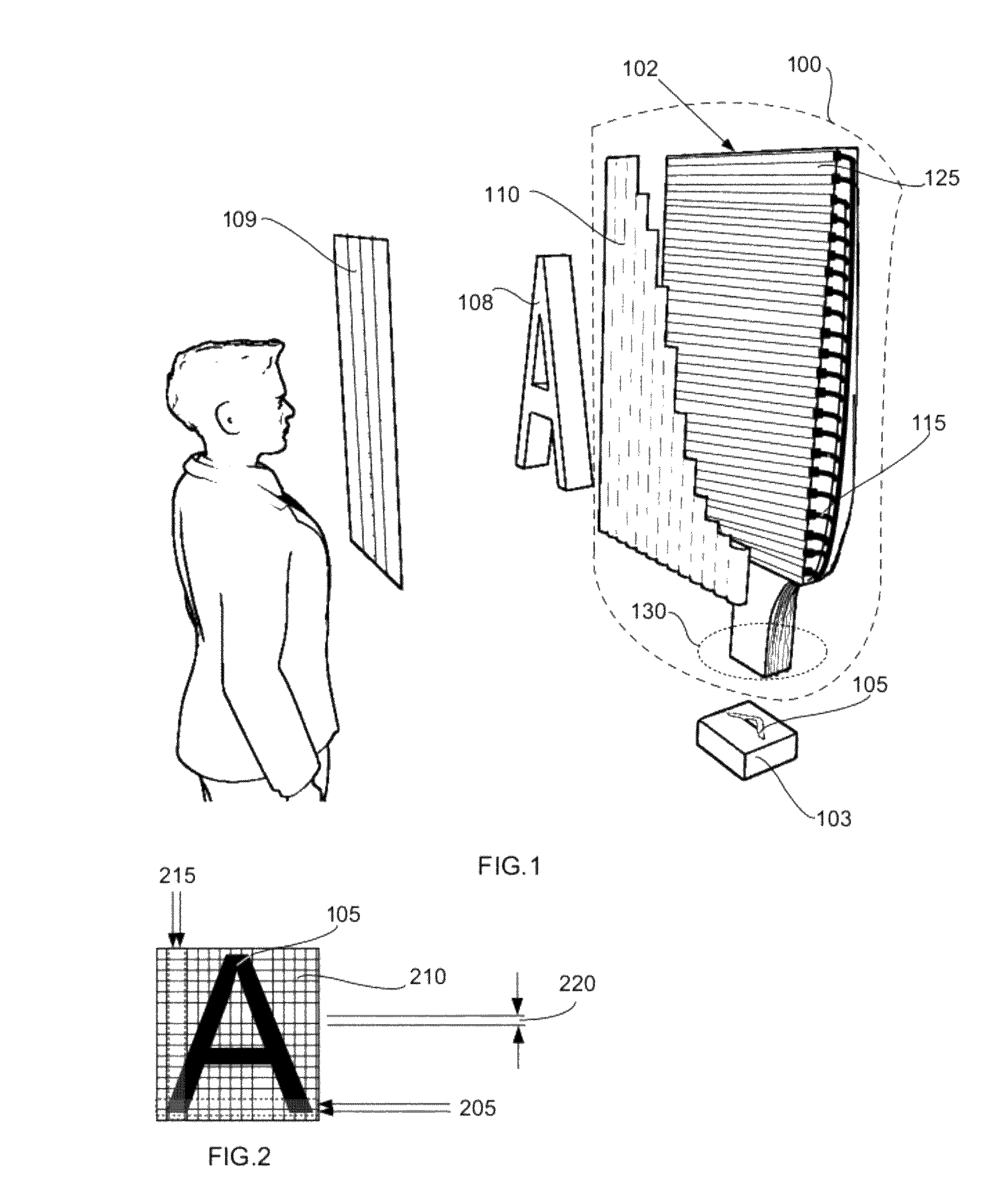
[0083]The principles of an operational image transforming device (100) involve receiving a projected two-dimensional image (105) made up of N×M pixels into M optical waveguides (405) within the receiving end (305) of each ribbon (115) in the stack (130) of ribbons. The received projected two-dimensional image (105) is then transformed to (N×S)×(M / S) pixels on the screen (102) where S is a number greater than one. For example, with S=4, which indicates four ribbons are placed adjacent to each other at their output end (310). If the projected two-dimensional image (105) has an array of 1920×1080 pixels, then the screen (102) emits an array of 1920×4=7680 pixels horizontally by 270 pixels vertically. This in contrast with current available optical fiber arrays like tapers and array-type light guiding bundles, which don't change the resolution.

[0084]The image transforming device (100) may include a lenticular (910) placed adjacent to the screen (102). Creating an auto-stereoscopic image...

example 2

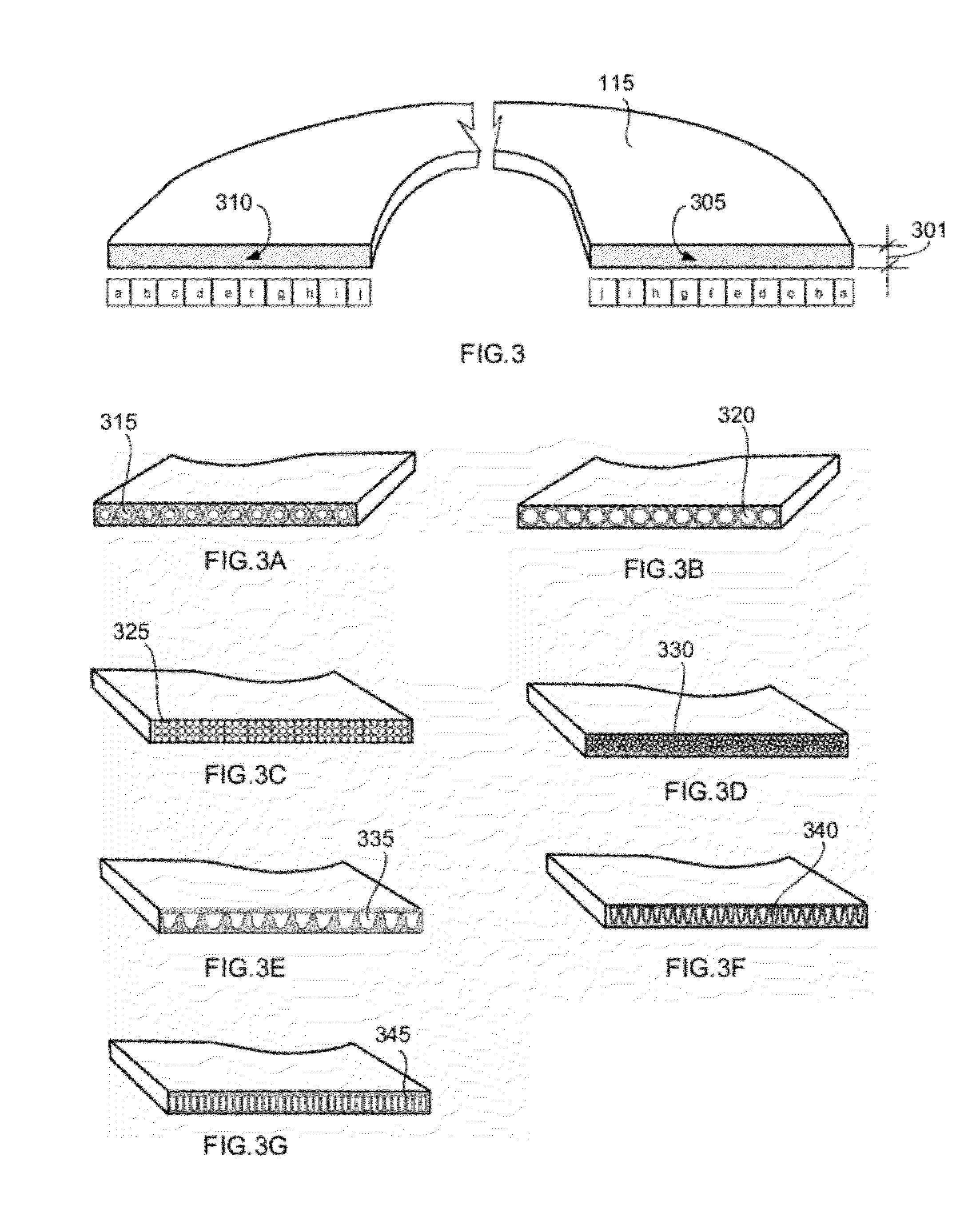
[0088]FIG. 9 illustrates how the end of each ribbon (115) is cut into a shape to improve the 3D image quality. Because each ribbon (115) is very thin, on the order of 0.05 mm, they can be cut with for example a 10 Watt carbon-dioxide laser using a lens with a 10 mm focal length that focuses the beam into a spot of 0.034 mm with a 0.2 mm focus depth. Cutting ribbons in this manner is not only fast and precise but also create a clean ribbon cross section. Adjusting the distance (905) between the emitting pixels and the lenticular (910) in this way can improve the viewing experience for an auto-stereoscopic display by reducing ghost images for example. The end face of the ribbon does not need to be cut perpendicular to the length of the ribbon, but may be cut at an angle such as the Brewster angle to improve the light coupling efficiency.

[0089]When the projected two-dimensional image (105) is projected in changing colors, the image transforming device (100) may take advantage of these ...

example 3

[0101]The image transforming device (100) in an auto-stereoscopic display can create an auto-stereoscopic image with (N×S / H) pixels horizontally and (M / S) pixels vertically, where H is the number of viewing zones, N is the number of pixels in the horizontal direction of the two-dimensional image (105), M is the number of pixels in the vertical direction of the two-dimensional image (105), and S is the first quantity of ribbons placed adjacent to each other on the spacer material (125) at the output end (310). The table below illustrates how the image transforming device (100) receives 0.05 mm square pixels can create different auto-stereoscopic displays using a received image of 1920×1080 pixels:

[0102]

H = # lenses = Vertical Screen Sviewing zonesHorz. Res.Resolutionsize23212054019.2 × 86.4 cm33218036028.8 × 57.6 cm42432027038.4 × 32.4 cm43224027038.4 × 32.4 cm

[0103]Because there are no electrical connections on or in the image transforming device (100) and all ribbons and spacers at...


PUM


Abstract

An image transforming device enables 3-D auto-stereoscopic display of a two-dimensional projected image. Optical waveguides in the form of ribbons are used. A stack of ribbons at a receiving end receives the projected image. A horizontal and vertical ribbon arrangement at the other end of the ribbon forms a screen for display of a transformed 3D image. A spacer material at the output end separates the vertical positioning of each ribbon. A screen may be assembled from the output ends of multiple devices forms. The two-dimensional image may be projected in changing colors. When changing colors are projected, the device may further include two lens arrays: a static micro-lens array and a dynamic array of micro-lenses, which is capable of motion synchronized with the changing colors.

Description

TECHNICAL FIELD[0001]In the field of optical systems, an image transforming device for use in an auto-stereoscopic display apparatus is disclosed. The device enables viewer perception with unaided eyes of three-dimensional images transformed from projected two-dimensional images. The device includes a plurality of transmitting elements and may include a lenticular.BACKGROUND ART[0002]Today's commercial auto-stereoscopic displays typically use a lenticular, also known as a lenticular screen, in front of an LCD (Liquid Crystal Display) flat panel display to create up to nine viewing zones. This low number makes it difficult to find the right position, and stay in the position, to be able to see the stereo image. The number of available pixels and their relative large size make creating more viewing zones result in an undesirable low resolution three-dimensional (3D) image. Commercial available displays come in standard formats such as the HDTV (High Definition Television) format havin...

Claims


Application Information

Patent Timeline
Patent Type & Authority Patents(United States)
IPC IPC(8): G06T15/00G02B30/27
CPCH04N13/0402H04N13/0404G02B27/2214G02B6/08H04N13/302H04N13/305G02B30/27
Inventor VAN NULAND, HENRICUS SERVATIUS FRANSISCUS
Owner VAN NULAND HENRICUS SERVATIUS FRANSISCUS
Why Eureka
Try Eureka