Thermally assisted magnetic head, head gimbal assembly, and hard disk drive
a technology of magnetic head and head gimbal, which is applied in the direction of combination recording, data recording, instruments, etc., can solve the problems of insufficient intensity of recording magnetic field generated, fading to realize hard disk drives with high transfer rate, etc., and achieves simple structure, shortening time elapse, and increasing the effect of effective refractive index
- Summary
- Abstract
- Description
- Claims
- Application Information
AI Technical Summary
Benefits of technology
Problems solved by technology
Method used
Image
Examples
first embodiment
[0096]To begin with, the first embodiment of the thermally assisted magnetic head, head gimbal assembly, and hard disk drive in accordance with the present invention will be explained.
Hard Disk Drive
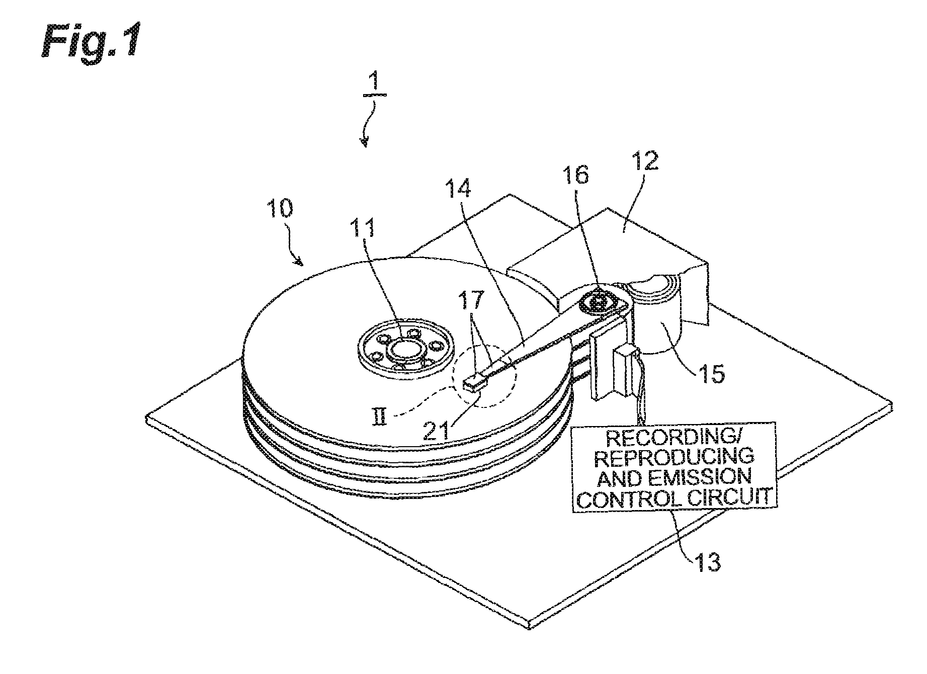
[0097]FIG. 1 is a perspective view of the hard disk drive in accordance with the embodiment.
[0098]The hard disk drive 1 comprises magnetic disks 10 which are a plurality of magnetic recording media rotating about a rotary shaft of a spindle motor 11, an assembly carriage device 12 for positioning thermally assisted magnetic heads 21 onto tracks, and a recording / reproducing and emission control circuit (control circuit) 13 for regulating writing and reading operations of the thermally assisted magnetic heads 21 and further controlling a laser diode which is a light source for generating laser light for thermally assisted magnetic recording which will be explained later in detail.
[0099]The assembly carriage device 12 is provided with a plurality of driving arms 14. These driving arms 14 ca...
second embodiment
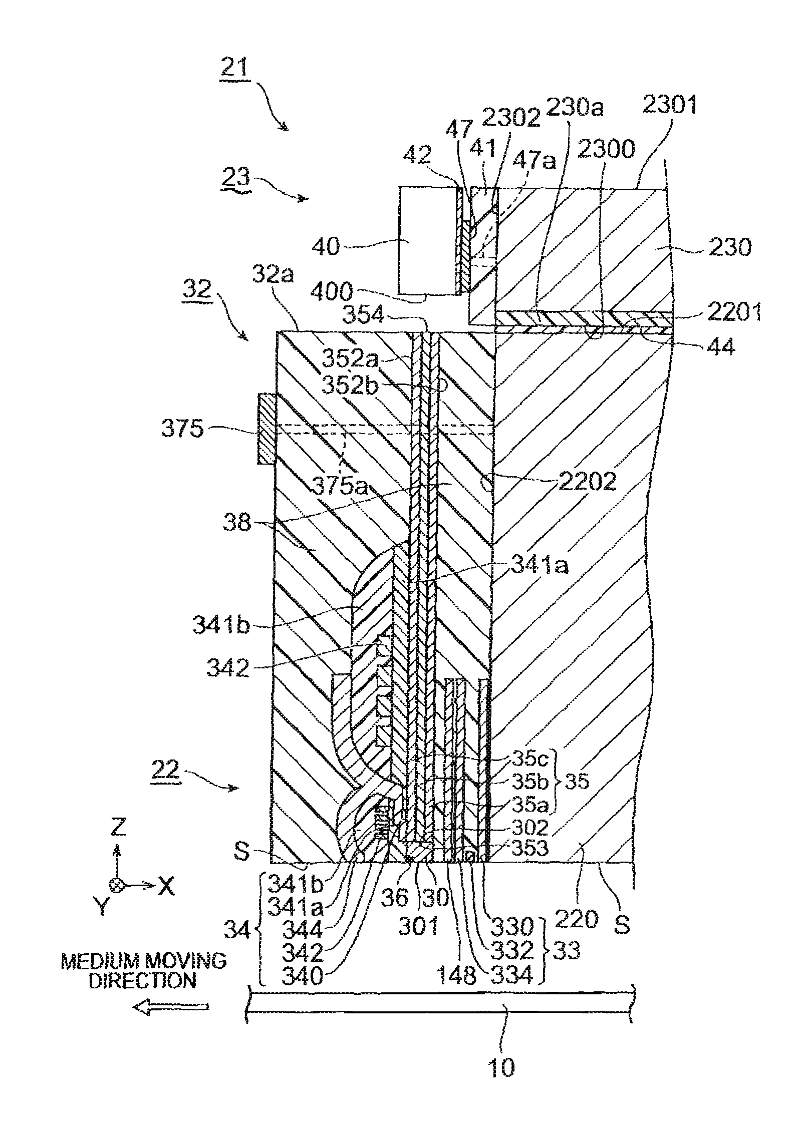
[0234]The second embodiment of the thermally assisted magnetic head, head gimbal assembly, and hard disk drive in accordance with the present invention will now be explained with reference to FIGS. 29 to 33. FIGS. 29 to 33 correspond to FIGS. 4, 6, 8, 9, and 13 in the first embodiment, respectively. The second embodiment differs from the first embodiment in terms of modes of the main magnetic pole 340, cores 30 and 35, and near-field light generating part 36.
[0235]As shown in FIGS. 29 and 30, the leading end 3401 of the main magnetic pole 340 and the light exit surface 353 of the core 35 are located deeper by R340 (R35) than the medium-opposing surface S as in the first embodiment. Also, as in the first embodiment, the core 30 is positioned between the light exit surface 353 of the core 35 and the medium-opposing surface S. Unlike the first embodiment, however, the main magnetic pole 340 is not in contact with the upper face 352a of the core 35, but coincides therewith in terms of t...
PUM
| Property | Measurement | Unit |
|---|---|---|
| distance | aaaaa | aaaaa |
| width | aaaaa | aaaaa |
| length | aaaaa | aaaaa |
Abstract
Description
Claims
Application Information
 - R&D
- Intellectual Property
- Life Sciences
- Materials
- Tech Scout
- Unparalleled Data Quality
- Higher Quality Content
- 60% Fewer Hallucinations
Browse by: Latest US Patents, China's latest patents, Technical Efficacy Thesaurus, Application Domain, Technology Topic, Popular Technical Reports.
© 2025 PatSnap. All rights reserved.Legal|Privacy policy|Modern Slavery Act Transparency Statement|Sitemap|About US| Contact US: help@patsnap.com


