MRI guided radiation therapy

a radiation therapy and guided radiation technology, applied in the field of radiotherapy, can solve the problems of collateral damage, inability to be completely representative, and the anatomical location of the tumor to mov

Active Publication Date: 2012-10-23
DEERFIELD IMAGING INC
View PDF12 Cites 32 Cited by
  • Summary
  • Abstract
  • Description
  • Claims
  • Application Information

AI Technical Summary

Benefits of technology

[0033]Preferably the radiation therapy is generated by a collimated radiation source which is rotated round the lesion, generally in conjunction with movement of the patient support, in a manner which controls the application of a required dose of radiation to the lesion while accommodating the shape of the lesion and the movement of the lesion.
[0040]Alternatively and more preferably, the system acts to generate a pattern of movement of the lesion during a normal breathing pattern and heart rate pattern at a set rate comfortable to the patient and acts to monitor the respiratory and / or the cardiac cycles during radiation therapy beam application to ensure that the respiration rate and / or the cardiac rate has not changed outside of the bounds set for the needed accuracy of the movement of the beam. If the respiration rate or cardiac rate has changed by a sufficient degree, the radiation therapy beam is either halt, or alternatively paused until the respiratory rate and the cardiac rate can locked onto again, and match the rate detected during the MR data acquisition for accurate prediction of lesion movement.

Problems solved by technology

Even though MRI provides good location of the tumor at the time of the measurement, these images are normally recorded two to three days prior to the treatment and so may not be completely representative of tumor location on the day of treatment.
This is because the movement of the patient over time can cause the anatomical location of the tumor to move.
This produces collateral damage and may have a significant impact of the quality of life of the patient.
An additional challenge to effective radiation treatment is the effect of motion of the tumor in the body due to respiratory and cardiac motion.
This results in tumor masses moving making the continuous accurate targeting for treatment difficult.
The problem with this is the non-compatibility of linear accelerators and MRI.
This arises because the magnetic field generated by the magnet of course interferes with the operation of the linear accelerator to an extent which cannot be readily overcome.

Method used


Image

  • MRI guided radiation therapy
  • MRI guided radiation therapy
  • MRI guided radiation therapy

Examples


Embodiment Construction

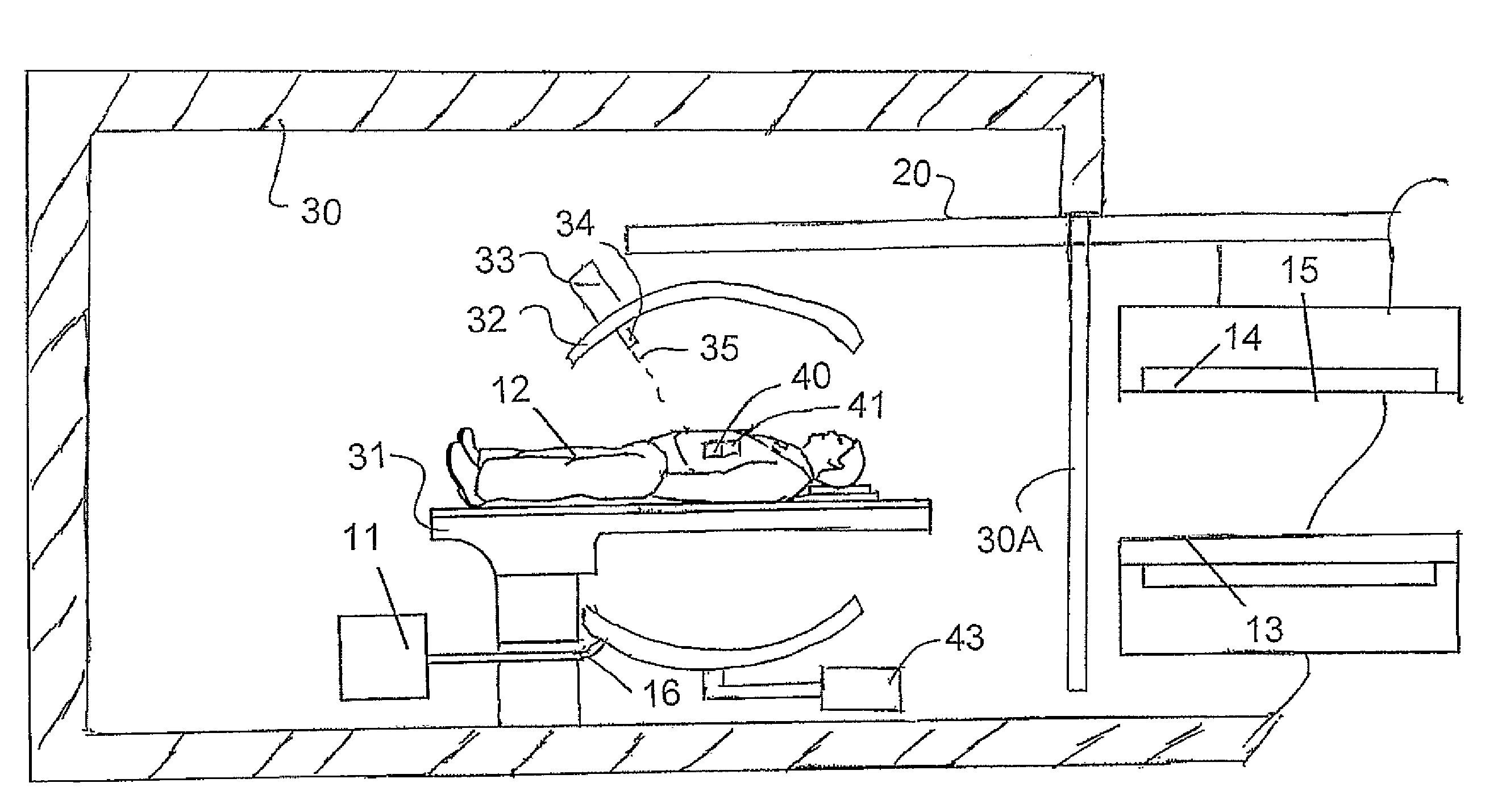
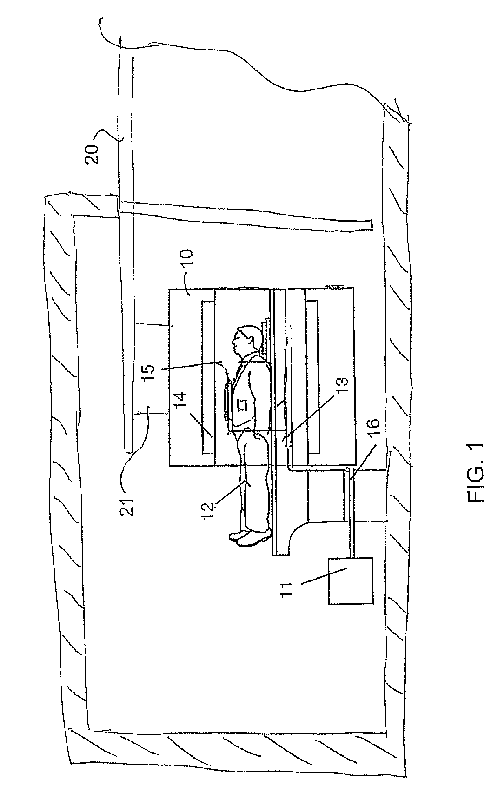
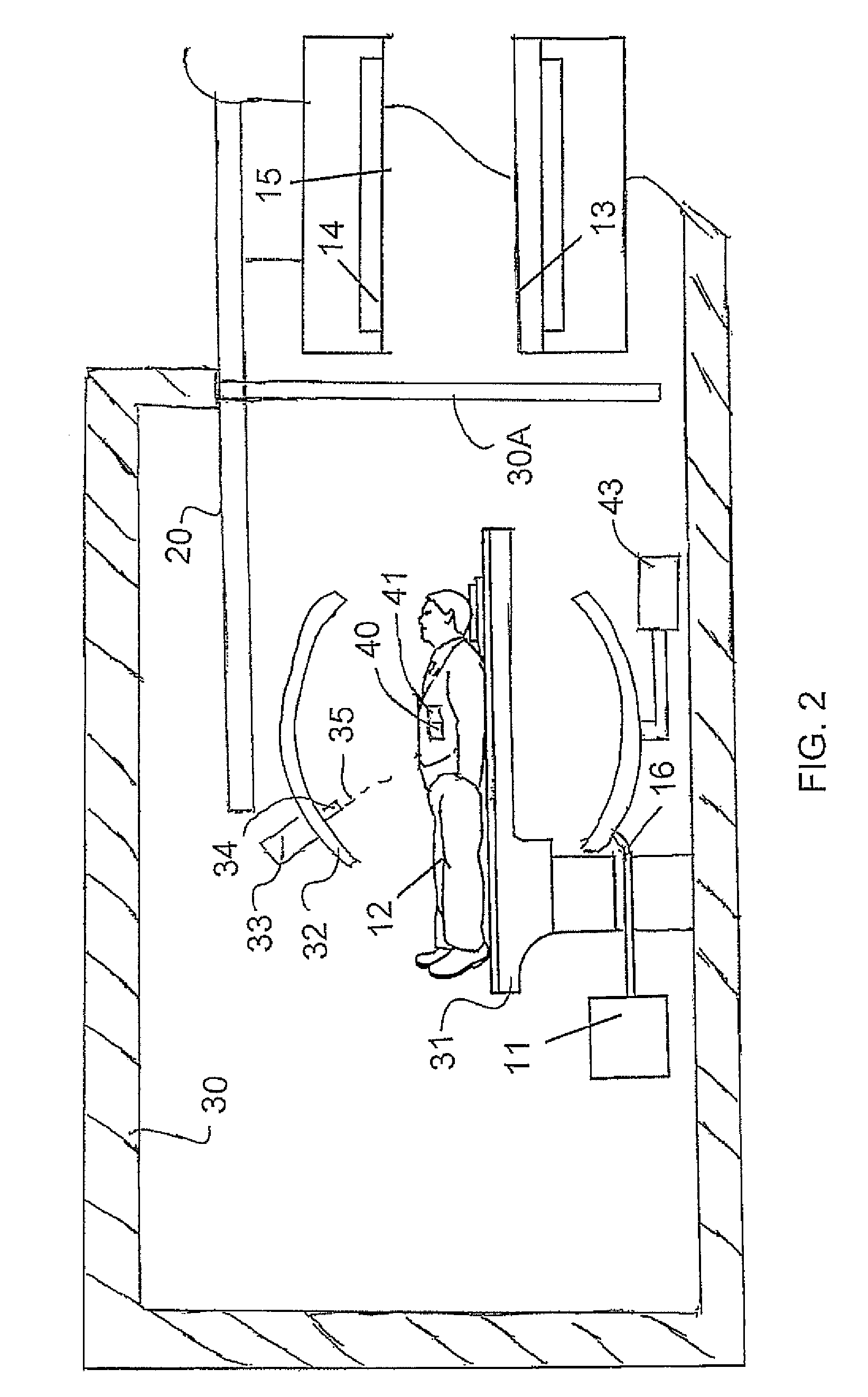
[0046]In FIG. 1 is shown schematically a magnetic resonance imaging system which includes a magnet 10 having a bore 11 into which a patient 12 can be received on a patient table 13. The system further includes an RF transmit body coil 14 which generates a RF field within the bore.

[0047]The movable magnet is carried on a rail system 20 with a support 21 suspended on the rail system. Further details of this construction as available from published US application 2008 / 0038712 published Feb. 14, 2008 assigned to the present assignees, the disclosure of which is incorporated herein by reference.

[0048]The system further includes a receive coil system generally indicated at 15 which is located at the isocenter within the bore and receives signals generated from the human body in conventional manner. A RF control system acts to control the transmit body coil 14 and to receive the signals from the receive coil 15.

[0049]The MRI system is used in conjunction with a patient radiation therapy sy...


PUM


Abstract

Radiation therapy of a lesion within a patient is guided to take into account movement of the lesion caused by respiration and / or cardiac effects by using MRI to image the patient while on the treatment support to obtain a series of images of a location of the lesion within the patient while obtaining data relating to respiration and / or cardiac function of the patient to generate lesion movement data as a function of respiration and / or cardiac function. After the magnet is removed from the bunker, during the radiation therapy, real time data relating to respiration and / or cardiac function of the patient is used to guide the radiation therapy using the lesion movement data obtained during the imaging.

Description

BACKGROUND OF THE INVENTION[0001]A radiotherapy device generally includes a linear electron beam accelerator which is mounted on a gantry and which can rotate about an axis which is generally parallel to the patient lying on the patient couch. During the radiation therapy, the patient is treated using either an electron beam or an X-Ray beam produced from the original electron beam. The electron or X-Ray beam is focused at a target volume in the patient by the combination of the use of a collimator and the rotation of the beam. The patient is placed on a couch which can be positioned such that the target lesion can be located in the plane of the electron beam as the gantry rotates in two directions.[0002]The objective of the radiation therapy is to target the lesion with a high dose of radiation over time and to have minimal impact on all the surrounding normal tissue. The first task is to precisely locate the tumor in three dimensional space. The best technique for this is MRI sinc...

Claims


Application Information

Patent Timeline
Patent Type & Authority Patents(United States)
IPC IPC(8): A61B5/055
CPCA61N5/1049G01R33/381G01R33/4808G01R33/5673A61N5/1067A61N2005/1055
Inventor SAUNDERS, JOHN K.GRAVES, DAVIDSCARTH, GORDON
Owner DEERFIELD IMAGING INC
Why Eureka
Try Eureka