Surface acoustic wave resonator, surface acoustic wave oscillator, and surface acoustic wave module unit

a technology of surface acoustic wave and surface acoustic wave, which is applied in the direction of oscillator, piezoelectric/electrostrictive device details, piezoelectric/electrostrictive/magnetostrictive devices, etc., can solve the problem that the characteristics of the surface acoustic wave resonator cannot be satisfactorily obtained, and achieve the effect of reducing power consumption

Active Publication Date: 2012-10-30
SEIKO EPSON CORP
View PDF16 Cites 2 Cited by
  • Summary
  • Abstract
  • Description
  • Claims
  • Application Information

AI Technical Summary

Benefits of technology

[0011]In this way, by weighting the IDT with the line occupying ratio, it is possible to enhance the confinement of vibration energy in the IDT, thereby implementing a surface acoustic wave resonator having a Q value more excellent than that of the conventional surface acoustic wave resonator. In this way, it is possible to reduce the size of the surface acoustic wave resonator.
[0013]According to this configuration, by setting the line occupying ratio to be larger than that at the center of the IDT, it is possible to lower the frequency.
[0015]According to this configuration, by disposing a region in which the line occupying ratio is constant at the center of the IDT, the vibration displacement at the center increases. The frequency at the edges of the IDT is set to be lower than that at the center of the IDT having a large vibration displacement by changing the line occupying ratio. Accordingly, it is possible to enhance the confinement of vibration energy in the IDT. When the ratio Nf / N of the number of pairs of electrode fingers Nf in the region in which the line occupying ratio is constant to the total number of pairs of electrode fingers N in the IDT is set to the above-mentioned range, it is possible to implement a surface acoustic wave resonator having a Q value more excellent than that of the conventional surface acoustic wave resonator.
[0021]According to this configuration, by using the crystal substrate having the Euler angle (−1° to +1°, 26.0° to 40.7°, 85° to 95°), it is possible to provide a surface acoustic wave resonator having an excellent frequency-temperature characteristic and an enhanced Q value.
[0023]According to this configuration, since the surface acoustic wave resonator having the enhanced Q value and the reduced CI value is mounted, it is possible to provide a surface acoustic wave oscillator in which the excitation of surface acoustic waves is stabilized and the power consumption is reduced.
[0025]According to this configuration, since the surface acoustic wave resonator having the enhanced Q value and the reduced CI value is mounted, it is possible to provide a surface acoustic wave module unit in which the excitation of surface acoustic waves is stabilized and the power consumption is reduced.

Problems solved by technology

With the decrease in the size of the surface acoustic wave resonator, there is a problem in that a decrease in Q value or an increase in CI value is caused and thus the characteristics of the surface acoustic wave resonator cannot be satisfactorily obtained.

Method used


Image

  • Surface acoustic wave resonator, surface acoustic wave oscillator, and surface acoustic wave module unit
  • Surface acoustic wave resonator, surface acoustic wave oscillator, and surface acoustic wave module unit
  • Surface acoustic wave resonator, surface acoustic wave oscillator, and surface acoustic wave module unit

Examples


first embodiment

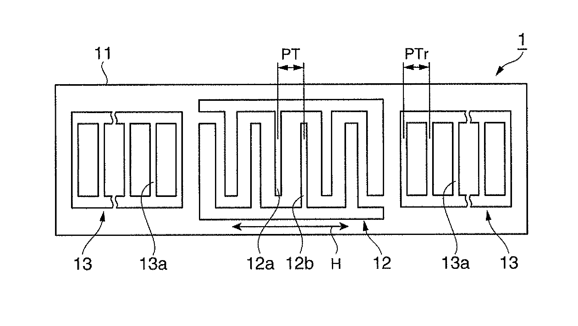
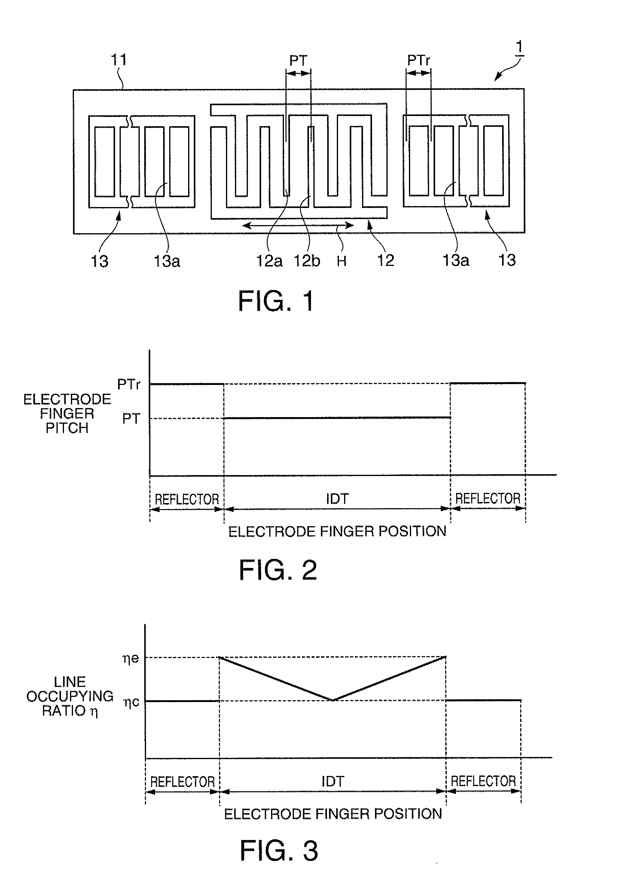
[0062]A surface acoustic wave resonator according to a first embodiment of the invention will be described below.

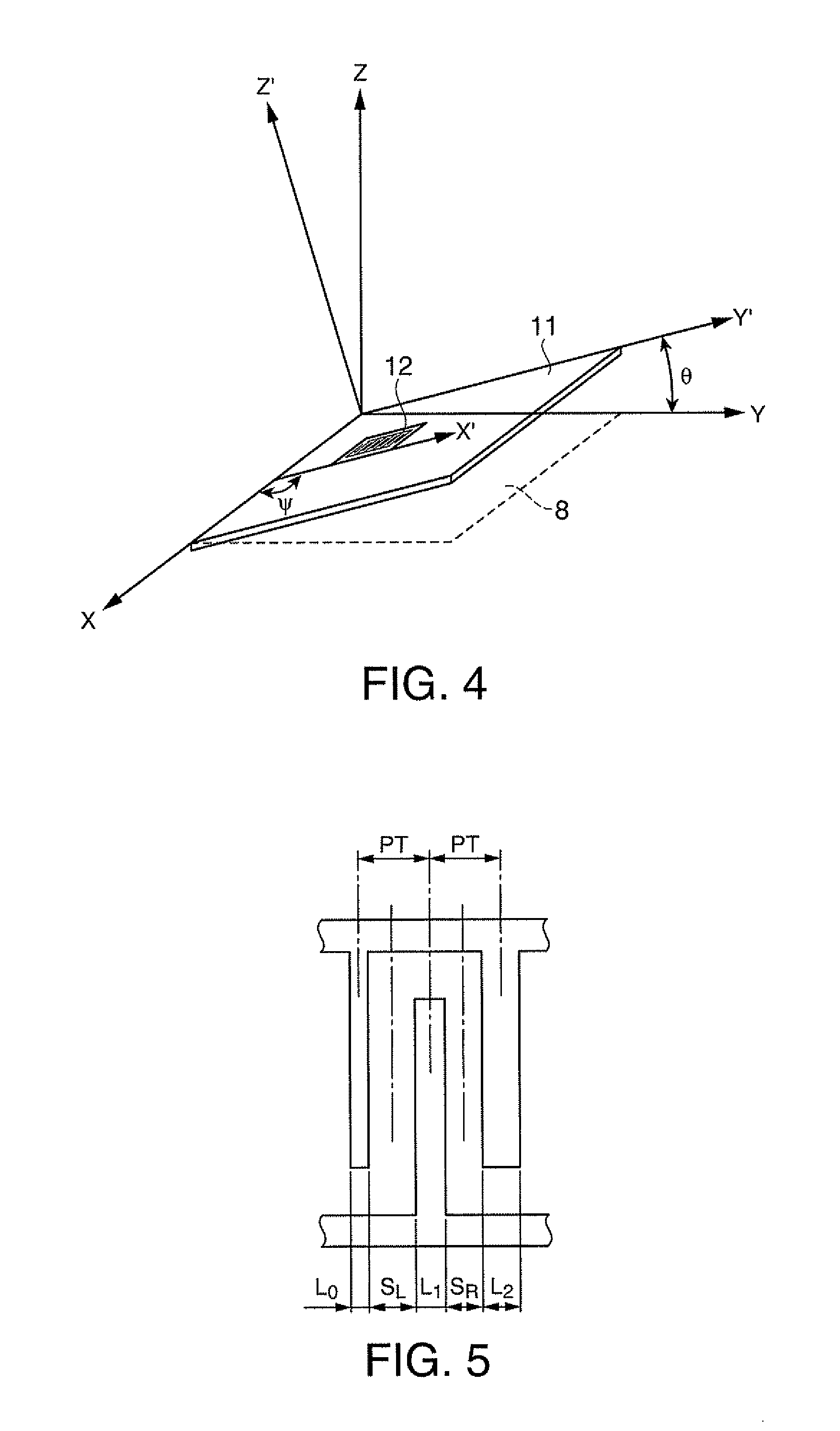
[0063]FIG. 1 is a plan view schematically illustrating the configuration of a surface acoustic wave resonator according to this embodiment. FIG. 2 is a diagram illustrating the relation between an electrode finger position and an electrode finger pitch in the surface acoustic wave resonator according to this embodiment. FIG. 3 is a diagram illustrating the relation between the electrode finger position and a line occupying ratio in the surface acoustic wave resonator according to this embodiment. FIG. 4 is a diagram illustrating a cutout angle of a crystal substrate and a traveling direction of surface acoustic waves. FIG. 5 is a diagram schematically illustrating the line occupying ratio.

[0064]As shown in FIG. 1, the surface acoustic wave resonator 1 includes an IDT 12 having a comb-like electrode and a pair of reflectors 13 disposed with the IDT 12 interposed therebetwe...

modification 1

(Modification 1)

[0096]A modification of the surface acoustic wave resonator according to the first embodiment of the invention will be described below.

[0097]In the first embodiment, the line occupying ratio of the reflectors is set to the same as the line occupying ratio at the center of the IDT. However, in this modification, the line occupying ratio of the reflectors is set to the same as the line occupying ratio at the edges of the IDT.

[0098]FIG. 8 is a plan view schematically illustrating the configuration of a surface acoustic wave resonator according to this modification. FIG. 9 is a diagram illustrating the relation between the electrode finger position and the electrode finger pitch in the surface acoustic wave resonator according to this modification. FIG. 10 is a diagram illustrating the relation between the electrode finger position and the line occupying ratio in the surface acoustic wave resonator according to this modification.

[0099]As shown in FIG. 8, a surface acoust...

modification 2

(Modification 2)

[0113]Another modification of the surface acoustic wave resonator according to the first embodiment of the invention will be described below.

[0114]In the first embodiment, the line occupying ratio of the reflectors is set to the same as the line occupying ratio at the center of the IDT. However, in this modification, the line occupying ratio of the reflectors is set to greater than the line occupying ratio at the edges of the IDT.

[0115]The configuration of the surface acoustic wave resonator according to this modification is almost the same as Modification 1 and thus will not be described in detail but in brief.

[0116]FIG. 12 is a diagram illustrating the relation between an electrode finger position and an electrode finger pitch in a surface acoustic wave resonator according to this modification. FIG. 13 is a diagram illustrating the relation between the electrode finger position and the line occupying ratio in the surface acoustic wave resonator according to this mo...


PUM


Abstract

It is possible to reduce the size of a surface acoustic wave resonator by enhancing the Q value. In a surface acoustic wave resonator in which an IDT having electrode fingers for exciting surface acoustic waves is formed on a crystal substrate, a line occupying ratio is defined as a value obtained by dividing the width of one electrode finger by the distance between the center lines of the gaps between one electrode finger and the electrode fingers adjacent to both sides thereof, and the IDT includes a region formed by gradually changing the line occupying ratio from the center to both edges so that the frequency gradually becomes lower from the center to both edges than the frequency at the center of the IDT.

Description

TECHNICAL FIELD[0001]The present invention relates to a surface acoustic wave resonator employing a piezoelectric substrate, a surface acoustic wave oscillator, and a surface acoustic wave module unit.BACKGROUND ART[0002]Conventionally, surface acoustic wave resonators using surface acoustic waves (SAW) have been widely used in electronic apparatuses.[0003]With the recent spread of portable devices, a decrease in the size of a surface acoustic wave resonator used therein has been required. With the decrease in the size of the surface acoustic wave resonator, there is a problem in that a decrease in Q value or an increase in CI value is caused and thus the characteristics of the surface acoustic wave resonator cannot be satisfactorily obtained.[0004]As a countermeasure, for example, PTL 1 discloses a technique of enhancing the Q value by reducing a ratio (a line width ratio or a line occupying ratio) of an electrode finger width to an electrode finger pitch in a comb-like electrode f...

Claims


Application Information

Patent Timeline
Patent Type & Authority Patents(United States)
IPC IPC(8): H01L41/04H03H9/64H03B5/30
CPCH03H9/02551H03H9/1071H03H9/0547
Inventor YAMANAKA, KUNIHITO
Owner SEIKO EPSON CORP
Why Eureka
Try Eureka