
Apparatus and method for processing beam information using low density parity check code

a parity check and optical information technology, applied in the field of apparatus and methods for processing optical information using low density parity check codes, can solve the problems of difficult hardware incorporation of ldpc codes, high bit error rate (ber), and errors on the data page, so as to improve the average accuracy of pixels, reduce the failure rate of decoding, and improve the effect of decoding performan

Active Publication Date: 2012-10-30
TAIWAN SEMICON MFG CO LTD
View PDF17 Cites 10 Cited by
  • Summary
  • Abstract
  • Description
  • Claims
  • Application Information

AI Technical Summary

Benefits of technology

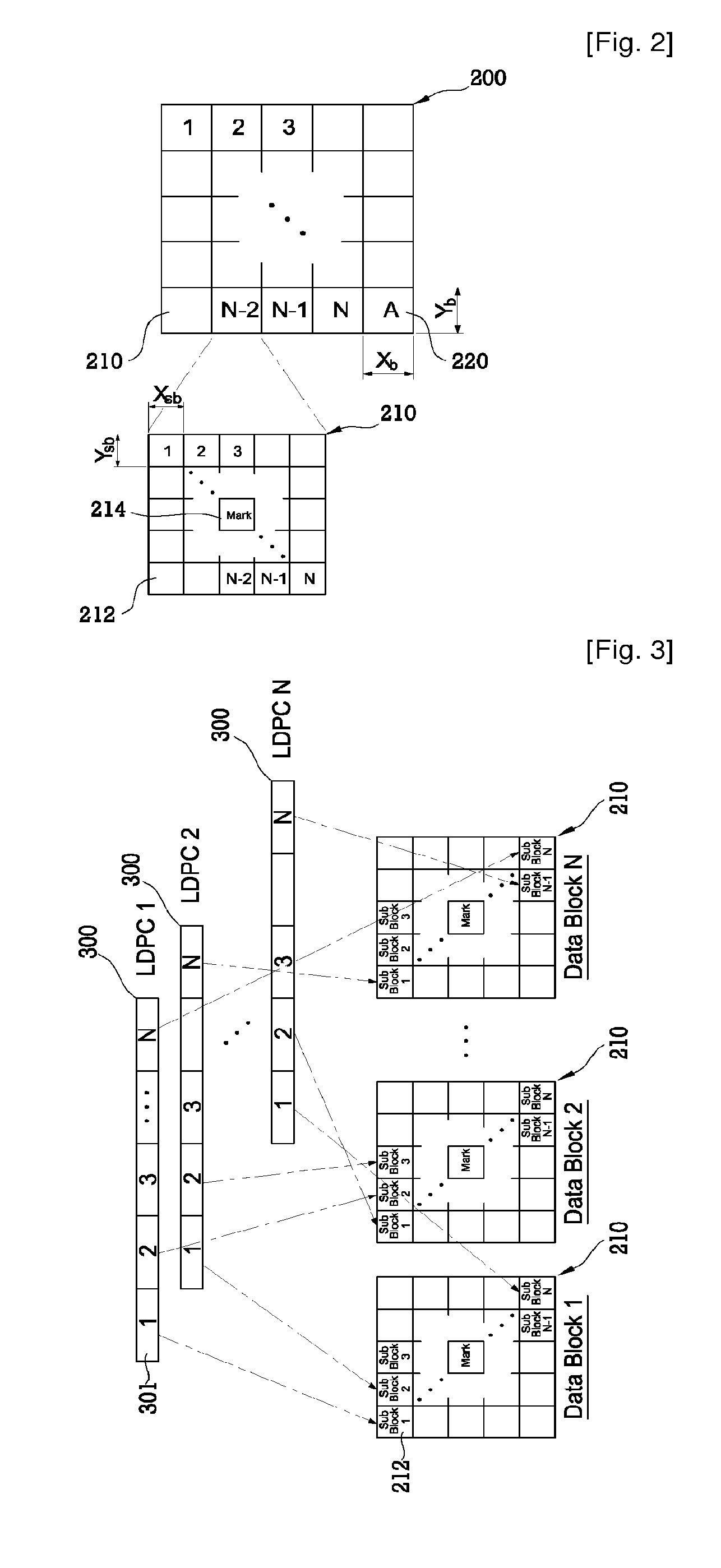
The patent describes an optical information recording apparatus and method for recording and reproducing data using holographic technology. The apparatus includes a beam source, an optical information detecting portion, and a decoding portion. The data is encoded into a low density parity check code and then mapped into a data page, which is recorded as hologram. The data page includes a data block with a mark at the center, which is used to calculate the reproduction probability of the data block. The apparatus can also include an encoding portion for dividing the data into a plurality of subblocks and mapping the low density parity check code into the data page. The method includes detecting the data page, identifying the address block, detecting the subblocks, and decoding the data from the subblocks. The technical effects of this patent include improved data recording and retrieval using holographic technology and improved reproducing apparatus and method.

Problems solved by technology

However, due to variations of channel characteristic such as contraction of the optical information recording medium, the detected data page may have errors when an image of data page is detected by the optical information detector.
These errors may cause a fairly high bit error rate (BER).
It is generally known that an irregular LDPC code has better error correction capacity but it is harder to embody by hardware than a regular LDPC code.

Method used


Image

  • Apparatus and method for processing beam information using low density parity check code
  • Apparatus and method for processing beam information using low density parity check code
  • Apparatus and method for processing beam information using low density parity check code

Examples


Embodiment Construction

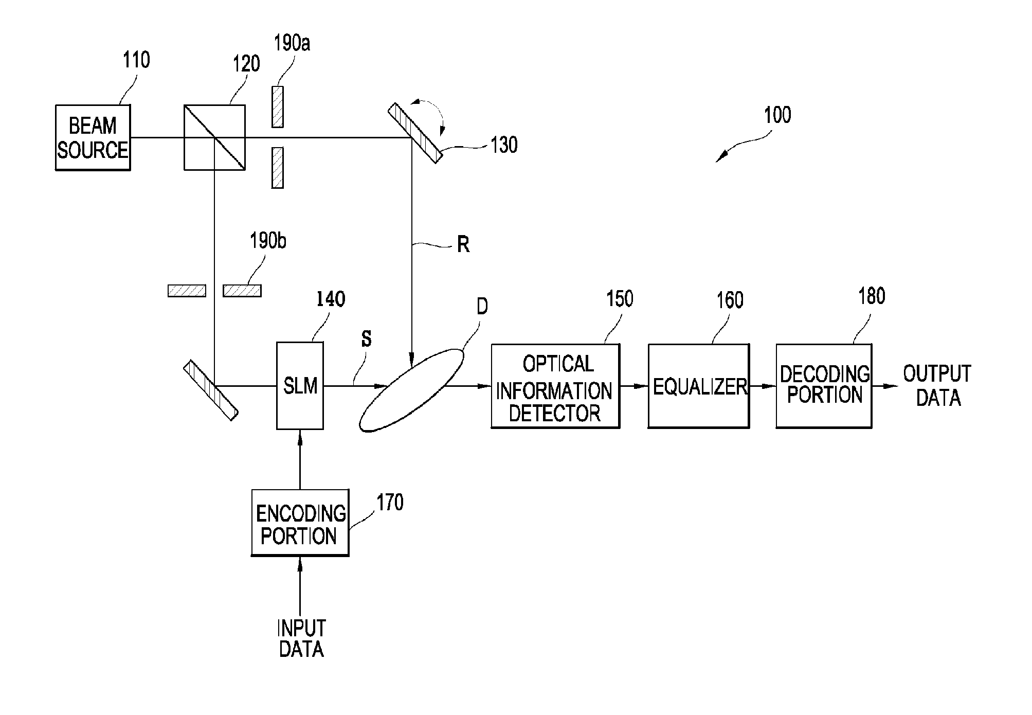
[0067]FIG. 1 shows a block illustrating an optical information recording / reproducing apparatus.

[0068]The optical information recording / reproducing apparatus 100 includes a beam source 110, a beam splitter 120. an angle multiplexer 130, a spatial light modulator 140, an optical information detector 150, an equalizer 160, an encoding portion 170 and a decoding portion 180, as shown in FIG. 1.

[0069]Light projected from the beam source 110 is split into a reference beam R and an information beam S through the beam splitter 120. The reference beam R goes through the first shutter 190a and is projected to optical data storage at the specific angle after it is reflected at the angle multiplexer 130.

[0070]In addition, the information beam S, where data is not loaded, goes through the second shutter 190b and is projected to the spatial light modulator 140 after its path is changed by a reflecting mirror.

[0071]Meanwhile, the spatial light modulator 140 represents binary data, which is receive...


PUM


Abstract

An apparatus and method for processing optical information using a low density parity check code are suggested. An optical information recording method includes the steps of encoding data to record into a low density parity check code; representing the data, which is encoded into the low density parity check code, to a spatial light modulator in the unit of a data page; and modulating a recording beam into the data page representing the spatial light modulator to be recorded in the form of hologram in a recording medium. By blocking inexact probability information from being concentrated in the LDPC code block, by achieving exact probability information through effective allocation of a mark, and by improving average accuracy of the pixel, which corresponds to the LDPC code, failure rate of decoding can be minimized so that decoding performance can be improved.

Description

TECHNICAL FIELD[0001]The present invention relates to an apparatus and method for processing optical information using a low density parity check code.BACKGROUND ART[0002]An optical information processing apparatus using the holography is a kind of page-oriented memories and uses a parallel signal processing as an input / output method. Accordingly, a holographic optical information processing apparatus can perform data processing faster than a CD (Compact Disk) or DVD (Digital Versatile Disk) which records or reproduces data by a bit.[0003]An optical information processing apparatus using the holography performs recording operation by projecting an information beam, which contains an image information of data to record, and a reference beam, which is to be interfered with the information beam, to an optical information recording medium (ex, optical data storage). In the other hand, for reproducing, the reference beam is projected to the optical information recording medium, a reprodu...

Claims


Application Information

Patent Timeline
Patent Type & Authority Patents(United States)
IPC IPC(8): H03M13/00G11C29/00
CPCG11B7/0065G11B20/1833H03M13/1102G11B2220/2504G11B7/004G11B20/18G11B20/10
Inventor CHUNG, BI WOONG
Owner TAIWAN SEMICON MFG CO LTD
Learn More