Industrial separator and dewatering plant

a technology of industrial separator and dewatering plant, which is applied in the direction of filtration separation, sedimentation settling tank, separation process, etc., can solve the problems of prior art not providing a solution to prevent wastewater, prior art not providing a solution to segregating filtered water from spray-off water, and prior art not providing a solution to possible overflow of water, so as to reduce input energy requirements, prevent contamination of a lower portion, and sufficient time

Active Publication Date: 2012-11-06
HYDRO INTERNATIONAL AG
View PDF82 Cites 34 Cited by
  • Summary
  • Abstract
  • Description
  • Claims
  • Application Information

AI Technical Summary

Benefits of technology

[0004]The debris captured by the filter cloth is driven downwardly into an open collection chamber which delivers the debris into the auger screw which conveys the debris to a compression chamber. Wash water that is not absorbed in the debris is free to flow above and around the auger's flights and by gravity flows toward and into the free water drain. The free water drain is located in an enclosed obstructed location so that only overflow liquid is able to freely flow into the drain. By allowing this drainage, a liquid level in the collection chamber is controlled and the dewatering drain located under the dewatering section is able to drain the remainder of water ab

Problems solved by technology

Belts commonly become clogged with the filtered material so that they require occasional or continuous cleaning.
However, the prior art does not provide a solution to preventing wastewater from collecting in the bottom of

Method used


Image

  • Industrial separator and dewatering plant
  • Industrial separator and dewatering plant
  • Industrial separator and dewatering plant

Examples


Embodiment Construction

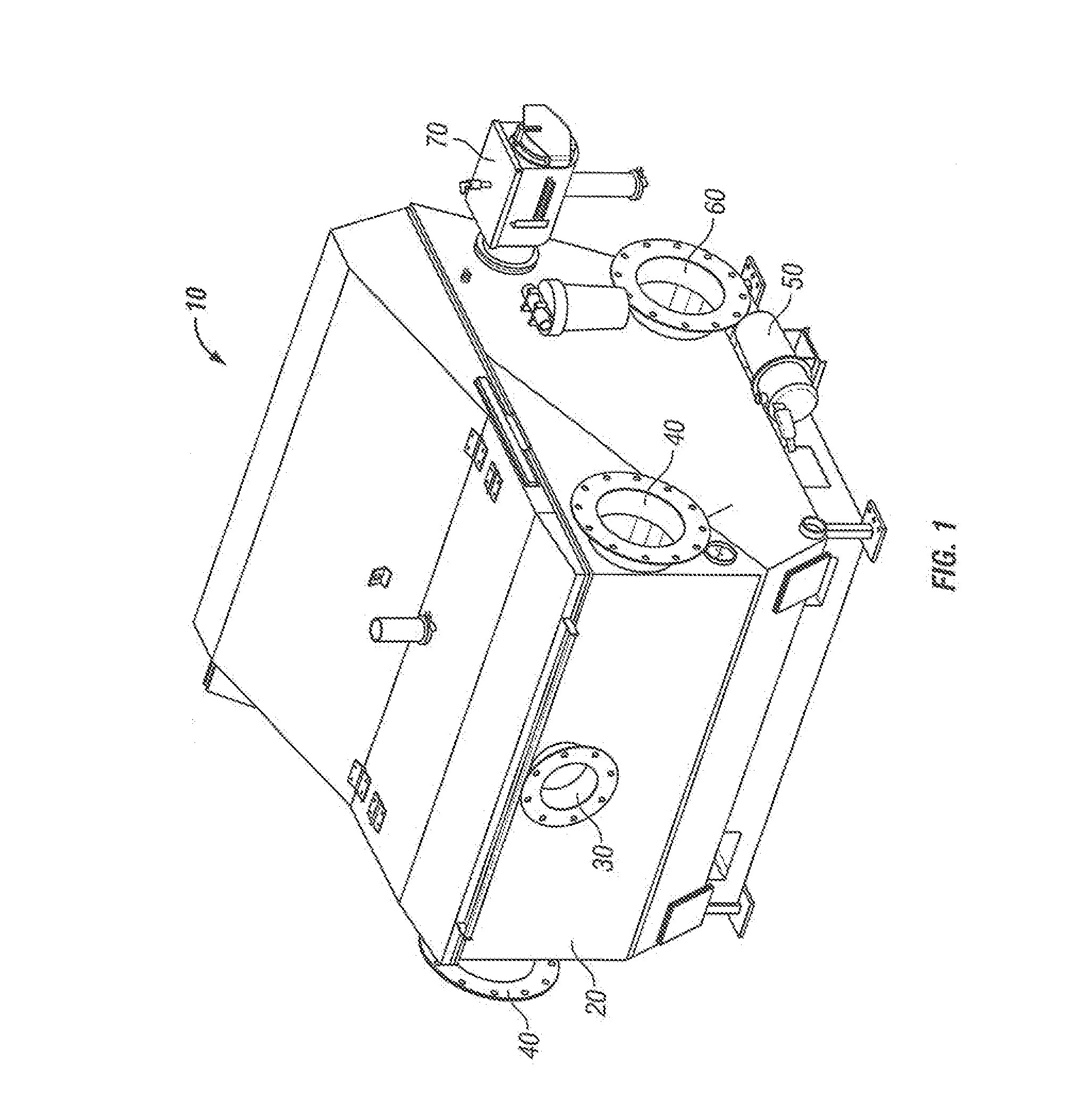
[0020]FIG. 1 illustrates an industrial separator and dewatering plant 10 used for processing wastewater 15A; see FIG. 7. Components of plant 10 are supported within and attached externally to a structural enclosure 20. Locations of a plant inlet 30 for receiving the wastewater 15A, wastewater overflow outlets 40, a wash water pump 50, an outlet 60 for filtered water 15B, and a dewatering device 70 are shown. Techniques for joining in-feed and out-feed conduits to elements 30, 40 and 60 are well known in the art.

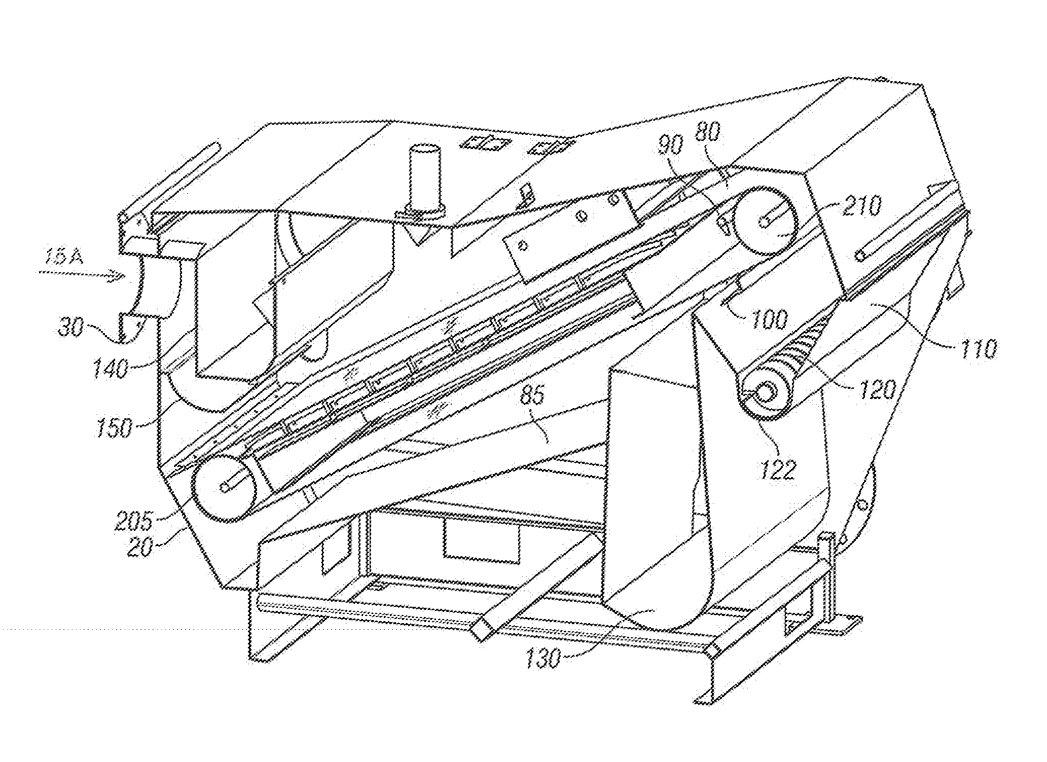
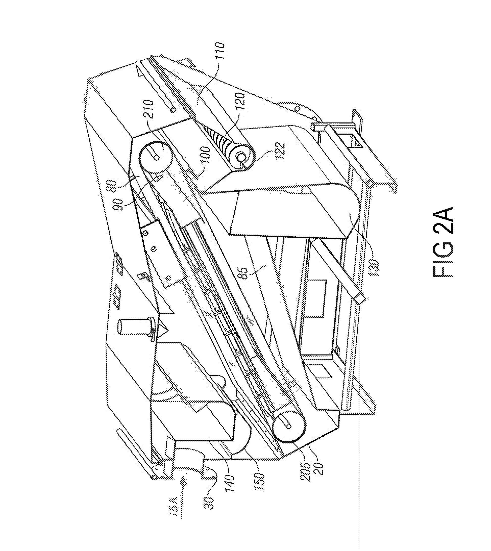
[0021]FIG. 2A shows locations of a conveyor belt 80 supported by a bottom 205 and a top 210 rollers, belt 80 being a fine mesh filter which has an upper belt portion 82 moving above a lower belt portion 84, a conveyor cavity 85 within which conveyor belt 80 operates, spray wash nozzle(s) 90, a belt scraper 100, a cake collection basin 110, an auger 120, collection manifold 130, a diverter panel 140, and a catch shelf 150. Wastewater inlet 30 is shown at the left in FIG. 2A.

[0...


PUM

PropertyMeasurementUnit
Kinetic energyaaaaaaaaaa

Abstract

An industrial separator and dewatering plant has a filtering portion using an inclined conveyor belt for carrying away a watery cake from an aqueous mixture containing solid matter. The filtering portion further has a wash water spray nozzle directed at the conveyor belt so as to dislodge the watery cake penetrated within the conveyor belt. A dewatering portion has a compression auger screw positioned for receiving the dislodged watery cake and the wash water. An auger screw receives the wash water and cake which is transported to a compression cage where compression drives water out of the cake leaving a semi-solid cake which is pressed against a door where it exits the plant.

Description

[0001]No federally sponsored research or development was used in the presented apparatus and method of use, and no reference to a sequence listing or table, a computer program listing or compact disc appendix is included herein.BACKGROUND OF THE DISCLOSURE[0002]This disclosure relates to the field of industrial filtering systems and more particularly to such a system that uses a continuous filter belt. Filter belts are often used to filter solid material from an aqueous mixture. Belts commonly become clogged with the filtered material so that they require occasional or continuous cleaning. Keeping the belt clean is critical to efficient operation and especially for continuous operation. The use of belt filters is well known in the art which teaches a variety of ways for ridding the filters of solid material. Once the filtered material has been removed from the filter belt it is known, for instance, to mechanically extract fluid via a screw press. Hot water and steam are known to be ...

Claims


Application Information

Patent Timeline
IPC IPC(8): B01D33/04B01D33/46B01D33/50B01D33/76
CPCB01D29/356B01D29/6476B01D33/04B01D33/41B01D33/76B30B9/12B30B9/127
Inventor MITCHELL, JOHN CHRISTOPHERSTEDMAN, KEN M.WALSER, GLENN EDWIN
Owner HYDRO INTERNATIONAL AG
Why Eureka
Try Eureka