Optical transceiver module

a transceiver module and optical technology, applied in the direction of optical elements, semiconductor lasers, instruments, etc., can solve the problems of increasing the number of parts and processing man-hours, difficult to achieve downsizing and cost reduction, and the process of axis alignment becomes complicated, so as to reduce the number of optical parts and mounting steps, the effect of sacrificing low-loss optical characteristics and high reliability

Inactive Publication Date: 2012-11-06
HITACHI LTD
View PDF28 Cites 31 Cited by
  • Summary
  • Abstract
  • Description
  • Claims
  • Application Information

AI Technical Summary

Benefits of technology

[0017]Embodiments of the present invention relate to an optical transmitter module that multiplexes light having plural wavelengths and transmits the multiplexed light, an optical receiver module that demultiplexes multiplexed light into individual wavelengths and receives the demultiplexed light, or a single-conductor bi-directional optical transceiver module. The embodiments provide an optical module that is capable of significantly reducing the number of optical parts and the number of mounting steps, permitting downsizing, and achieving a high yield without sacrificing low-loss optical characteristics and high reliability. The embodiments also provide a method for manufacturing such an optical module.

Problems solved by technology

At the same time, however, this also increases the number of parts and the number of processing man-hours, thereby making it difficult to achieve downsizing and cost reduction.
Further, the process of axis alignment becomes complicated.
This makes downsizing and cost reduction more difficult.Non-patent document 1: IEICE Technical Report, Vol. 107, No. 7, R2007-2, pp.

Method used


Image

  • Optical transceiver module
  • Optical transceiver module
  • Optical transceiver module

Examples


first embodiment

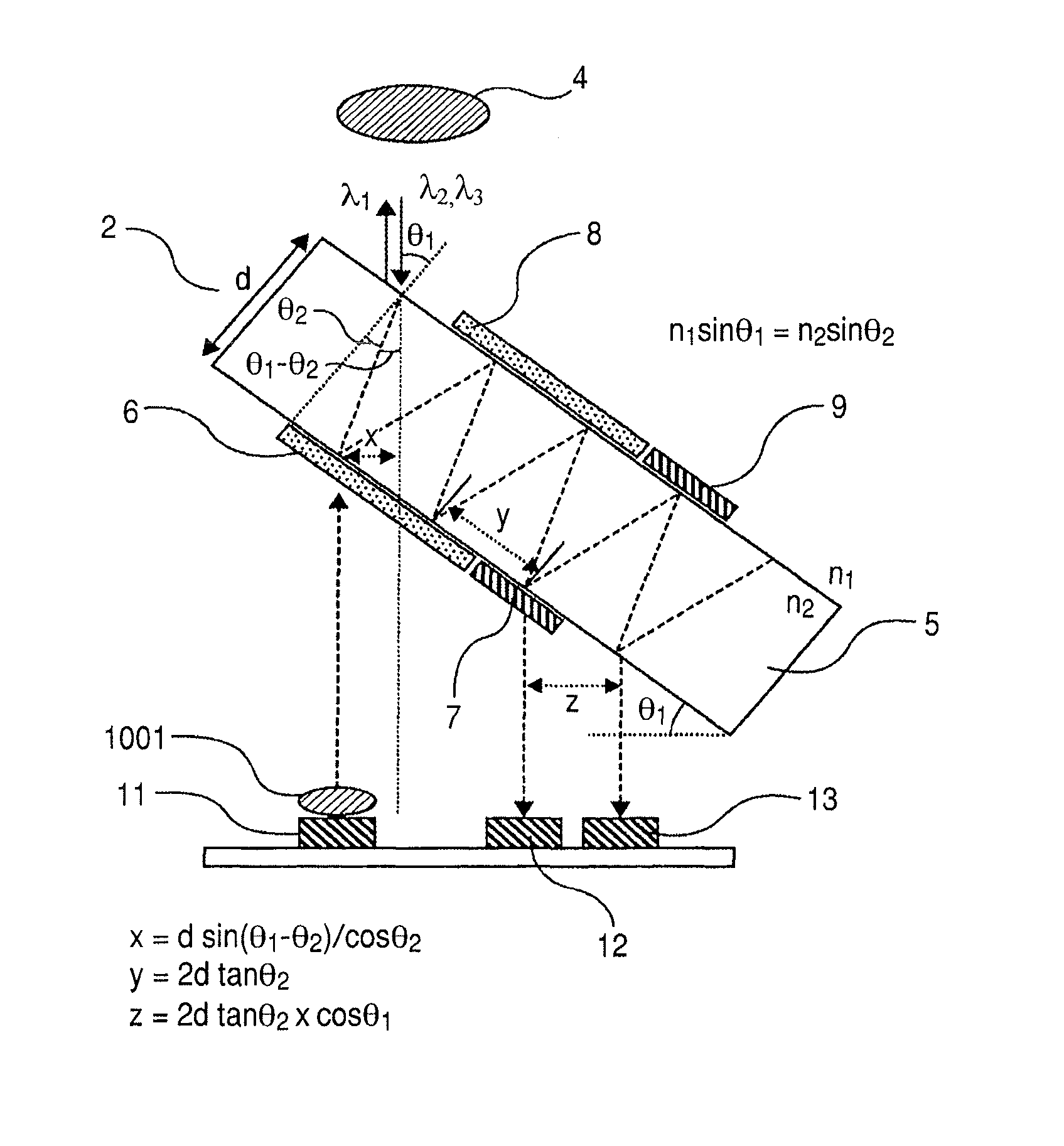
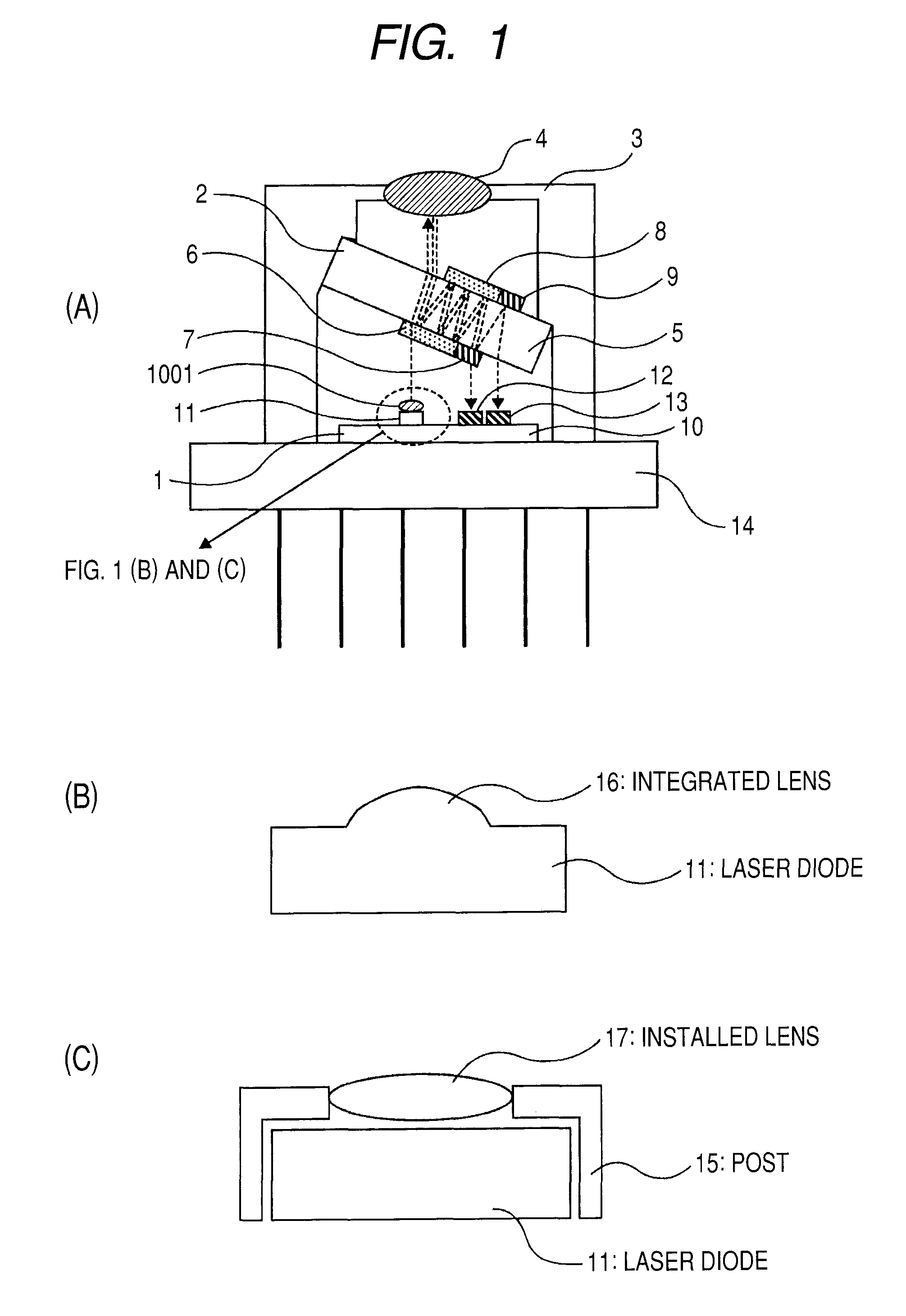
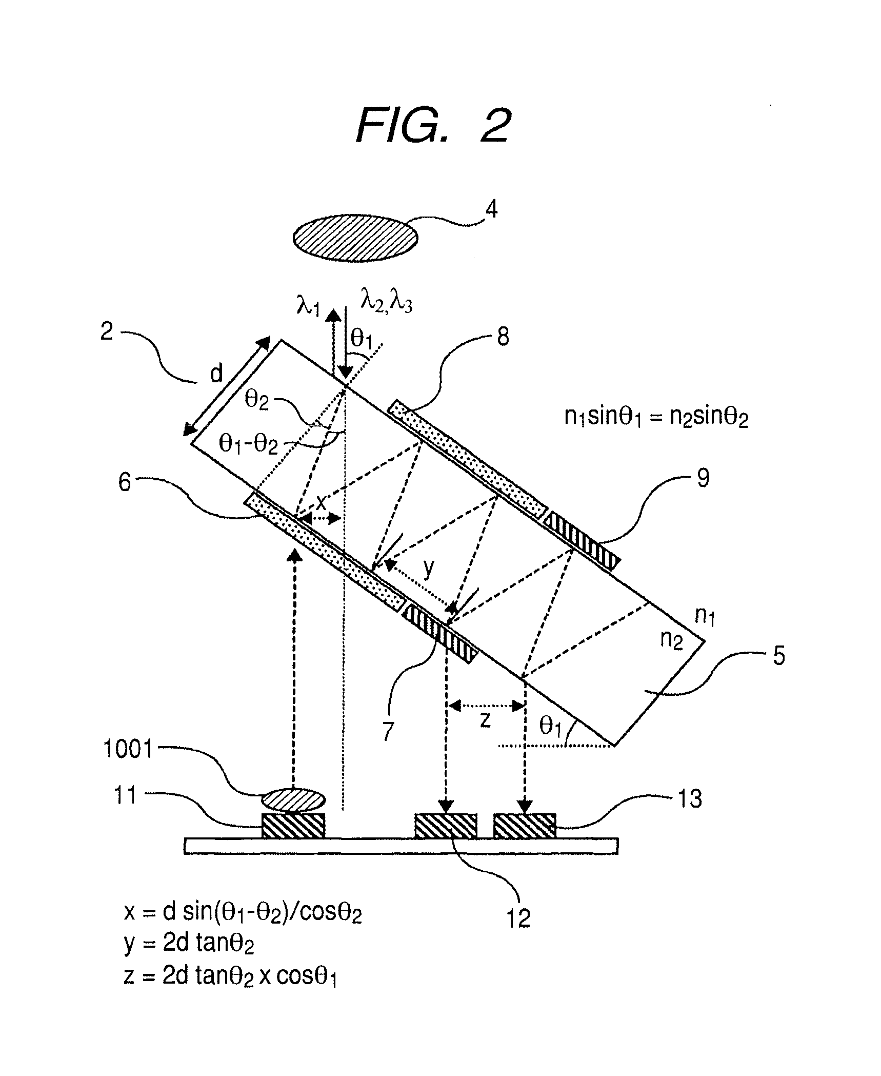
[0019]FIG. 1 are cross-sectional views of an optical module according to a first embodiment of the present invention. The present invention shown in FIG. 1 is applied to a so-called optical triplexer module, which is a bi-directional optical transceiver module using three wavelengths.

[0020]FIG. 1 show an example in which the module is mounted in a CAN package. An optical device mounting substrate 1 is mounted on a CAN stem 14. The optical device mounting substrate 1 includes a sub-mount 10 on which a laser diode 11 and photodetectors 12, 13 are mounted. An optical multiplexer / demultiplexer 2 is mounted on a CAN cap 3. A lens 1001 is positioned near the laser diode 11 or monolithically integrated with the laser diode 11. Operating wavelengths used by the laser diode 11 and the photodetectors 12, 13 are λ1, λ2, and λ3, respectively. The relationship between their lengths is given by the expression λ123. From left to right in FIG. 1, the laser diode and photodetectors are arranged in t...

second embodiment

[0031]FIG. 3 is a cross-sectional view of the optical module according to a second embodiment of the present invention. The present invention shown in FIG. 3 is applied to a dual-wavelength, single-conductor, bi-directional (BIDI) optical module. The optical module according to the second embodiment has the same basic configuration and functionality as the optical module according to the first embodiment. However, the second embodiment includes only one photodetector 30 and uses two operating wavelengths. Therefore, the second embodiment is merely provided with one wavelength-selective filter 26 and one mirror 27.

third embodiment

[0032]FIG. 4 is a cross-sectional view of the optical module according to a third embodiment of the present invention. This figure illustrates a module configuration where a single-mode fiber 93 is coupled to a CAN package 92 in which the optical system according to the first embodiment is mounted.


PUM


Abstract

The optical module includes an optical device mounting substrate 1 and an optical multiplexer / demultiplexer 2. One laser diode and at least one photodetector, which are positioned in the same plane, are mounted on the optical device mounting substrate 1. The optical multiplexer / demultiplexer is prepared by mounting a wavelength-selective filter and a mirror on the front and back surfaces of a transparent substrate. The optical device mounting substrate and the optical multiplexer / demultiplexer are mounted in a package 3 in such a manner that the optical device mounting surface and the filter surface are not parallel to each other. The optical module also includes a first lens, which is positioned near the laser diode or monolithically integrated with the laser diode, and a second lens, which converges light coming out of the optical multiplexer / demultiplexer toward an optical fiber.

Description

TECHNICAL FIELD[0001]The present invention relates to an optical transceiver module, and more particularly, to a bi-directional optical transceiver module that multiplexes or demultiplexes light having multiple wavelengths.BACKGROUND ART[0002]In the field of information and communication, the communication traffic for exchanging a large amount of data at a high speed by using light has been improved rapidly in recent years. Particularly, the use of broadband access lines has been accelerated in accordance with the explosive growth of the Internet, and FTTH (Fiber To The Home) services have been significantly established in the market. Among optical transmission systems of FTTH, the PON (Passive Optical Network) system, which allows plural subscribers to share one optical fiber, is now enjoying an increasing demand. The PON system receives data transmitted from a central office through one optical fiber, branches the received data to 16 to 32 optical fibers by using a splitter, and d...

Claims


Application Information

Patent Timeline
Patent Type & Authority Patents(United States)
IPC IPC(8): G02B6/36G02B6/38
CPCG02B6/4204G02B6/4246H01L31/0232H01L31/153H04B10/40G02B6/29367G02B6/32H01S5/02248H01S5/02284H01S5/02288H01S5/02292H01S5/0267H01S5/0687H01S5/005H01L31/02325H01S5/02255H01S5/02253H01S5/02325H01S5/02251
Inventor ADACHI, KOICHIROHOSOMI, KAZUHIKOSUGAWARA, TOSHIKI
Owner HITACHI LTD
Why Eureka
Try Eureka