Method and apparatus for removal of tissue

a tissue and tissue technology, applied in the field of surgical instruments, can solve the problems of cartilage perforation, femoral head collapse, target necrotic bone,

Inactive Publication Date: 2012-11-06
HOWMEDICA OSTEONICS CORP
View PDF55 Cites 25 Cited by
  • Summary
  • Abstract
  • Description
  • Claims
  • Application Information

AI Technical Summary

Problems solved by technology

The lesion will grow until there is insufficient structural support of the subchondral bone and the femoral head collapses in the load bearing area.
This will lead to collapse of the femoral head.
The procedure only moderately targets the necrotic bone and does not remove all necrotic regions.
The use of a trephine or drill to perform core decompression also has the risk of perforating the cartilage if the trephine or drill is inserted too deeply.
This procedure is performed under fluoroscopy to avoid perforation, which increases the radiation exposure for the surgeon.
The alternation between the burr and endoscope is repeated many times, which significantly slows the procedure.
In addition, since the cutting is not performed under real-time, direct visualization, the risk of penetrating the subchondral bone and perforating the articular cartilage as well as the removal of healthy bone is very high.
In addition, the reach of the burr of the typical instrument used for bone decompression beyond the walls of the osseous tunnel is limited by the amount the shaft of the burr can be angled within the tunnel, thereby preventing the removal of all necrotic bone.
In addition to being particularly invasive, such bone decompression technique is slow, and risks perforating the articular cartilage and removal of healthy bone.
Although this fibular grafting procedure has a relatively high success rate, which is attributable to the increase of blood flow in the femoral head, the duration of the surgical procedure is relatively lengthy, and may last up to four hours.

Method used


Image

  • Method and apparatus for removal of tissue
  • Method and apparatus for removal of tissue
  • Method and apparatus for removal of tissue

Examples


Embodiment Construction

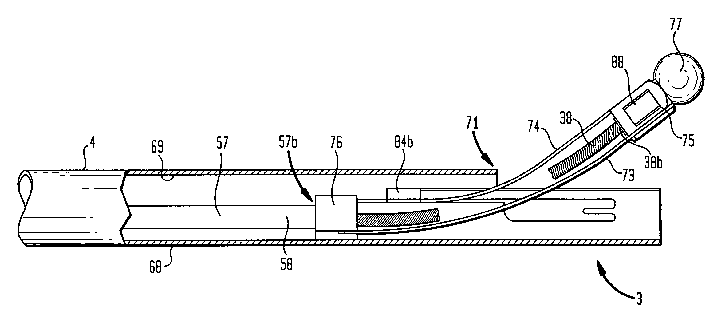
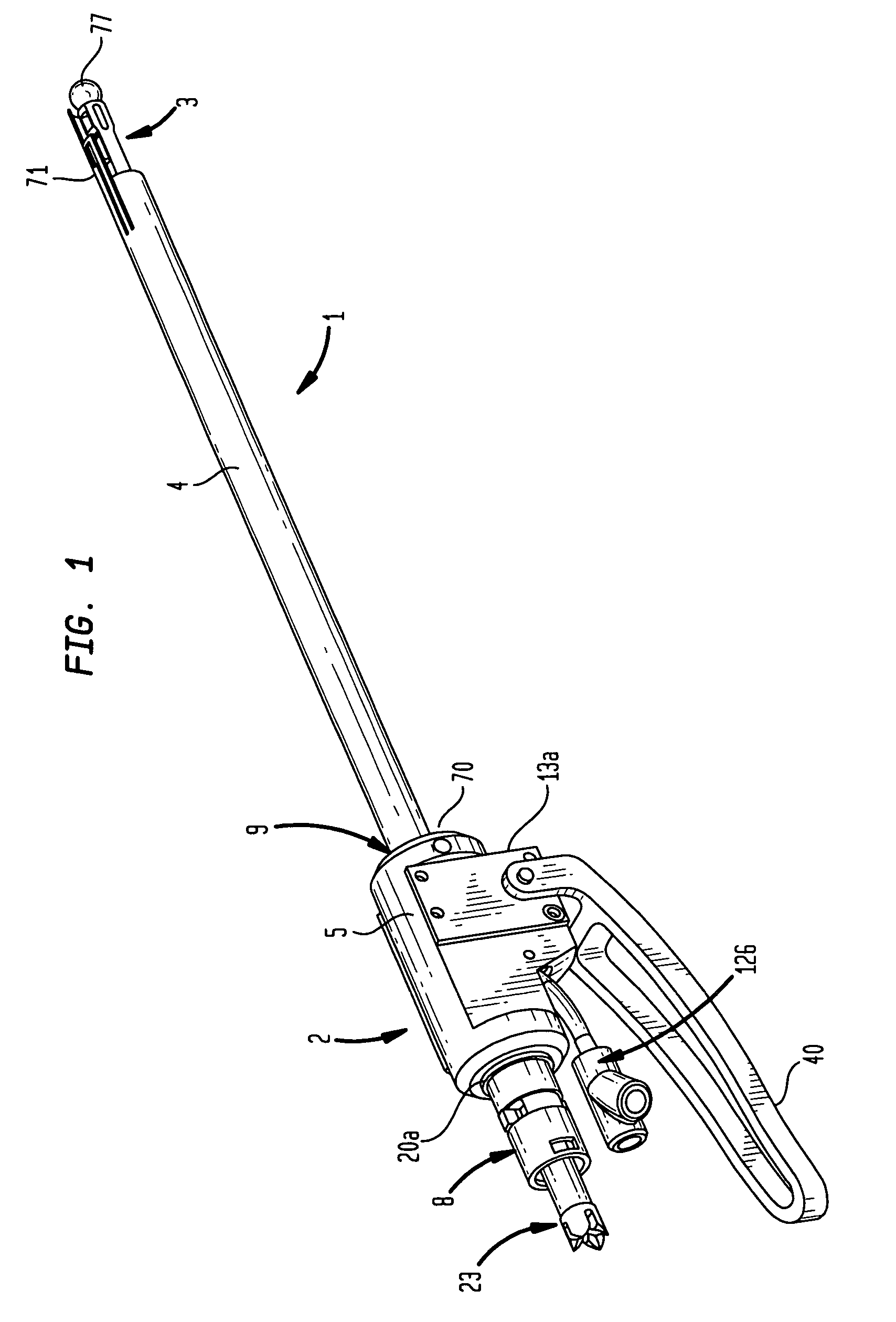
[0038]FIG. 1 is an exemplary surgical instrument 1 for removal of tissue, such as necrotic bone tissue from the femoral head of a hip joint, in accordance with an aspect of the present invention. The instrument 1 is operable for precise and selective removal of bone tissue within and outside a circumferential region defined by the distal end of the instrument 1. Referring to FIG. 1, the instrument 1 includes a power drive portion 2 on a first end 70 of a main tube 4 and an articulating cutting burr portion 3 on a second end 71 of the main tube 4.

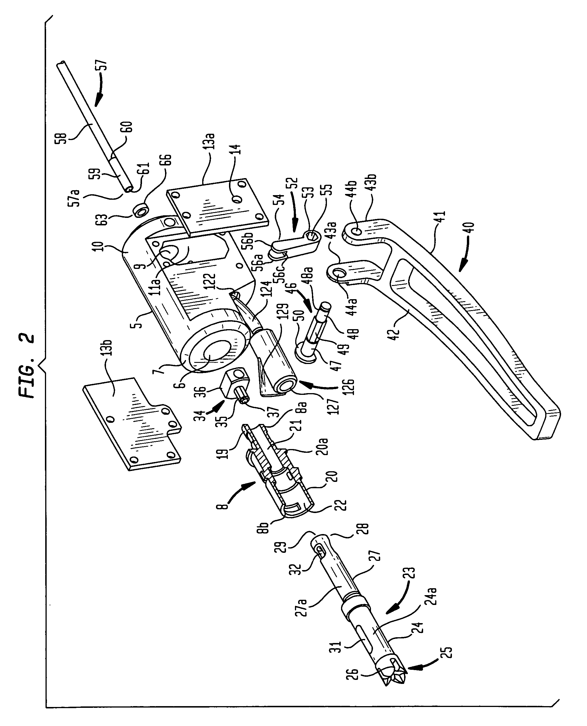
[0039]Further referring to FIGS. 2, 3 and 4, the power drive portion 2 includes a main housing 5, a driver coupling connector 8, a drive fitting 23, a flexible shaft fitting 34, a lever 40, a hinge pin 46, a thrust fork 52, a thrust collar 63 and a thrust tube 57. The housing 5 includes a first bore 6 on a first end 7 for coupling with the driver connector 8, and a second bore 9 on a second end 10 opposite the first end 7 for coupling with t...


PUM


Abstract

A surgical instrument includes a deflectable cutting element extending from the distal end of the instrument. The deflection of the cutting element is controllable based on a user operating a moveable member of the instrument. The deflectable cutting element is normally disposed within a circumferential region defined by the distal end of the instrument. The moveable member can be moved in relation to the instrument to deflect the deflectable cutting element, such that the cutting element is at least partially outside of the circumferential region. The extent that the cutting element is outside of the circumferential region is a function of the position to which the moveable member is moved in relation to the instrument. The instrument further includes direct imaging of the distal end, such that the deflection of the cutting element for selective removal of bone tissue at the distal end of the instrument can be controlled in real-time.

Description

FIELD OF THE INVENTION[0001]The present invention relates to method and apparatus for tissue removal and, more particularly, a surgical instrument having a deflectable cutting element, and method for using same, for selectively removing tissue.BACKGROUND OF THE INVENTION[0002]The treatment of diseases of long bones often requires the removal of a portion or all of the diseased bone.[0003]For example, removal of necrotic bone tissue is considered to be an important part of the treatment of osteonecrosis of the femoral head. Osteonecrosis of the femoral head is a disease caused by the occlusion of blood flow to or within the femoral head, which leads to the progressive necrosis of bone in the load bearing region. In osteonecrosis, as the bone dies, a lesion is formed below the subchondral bone. The lesion will grow until there is insufficient structural support of the subchondral bone and the femoral head collapses in the load bearing area. Early detection and intervention, particular...

Claims


Application Information

Patent Timeline
Patent Type & Authority Patents(United States)
IPC IPC(8): A61B17/16A61B17/32
CPCA61B17/1668A61B17/320016A61B17/32002A61B17/1617A61B19/5212A61B2017/2927A61B2017/320032A61B2019/5217A61B2217/005A61B2217/007A61B90/361A61B2090/3614
Inventor LYNCH, MICHAEL D.COLLAZO, CARLOS E.CHEN, ANGRANER, BRIAN
Owner HOWMEDICA OSTEONICS CORP
Why Eureka
Try Eureka