Travel way measurement system

Active Publication Date: 2012-11-06
STARODUB
View PDF8 Cites 78 Cited by
  • Summary
  • Abstract
  • Description
  • Claims
  • Application Information

AI Technical Summary

Benefits of technology

[0084]A method of selective SF GPR antenna array element utilization based on speed, resolution and signal processing requirements are used to maximize data sampling relative to vehicle acquisition speed and to enhance system resolution, including providing super-resolution capabilities. This super-resolution method provides sharper, more focused images than classical methods provide. Method uses combinations of transmitter and receiver pairs to efficiently and conveniently collect data for MUSIC signal processing implementation or other vector based array

Problems solved by technology

The speed, accuracy and reliability available to generate these measurements are currently inadequate to meet the evolving e

Method used


Image

  • Travel way measurement system
  • Travel way measurement system
  • Travel way measurement system

Examples


Embodiment Construction

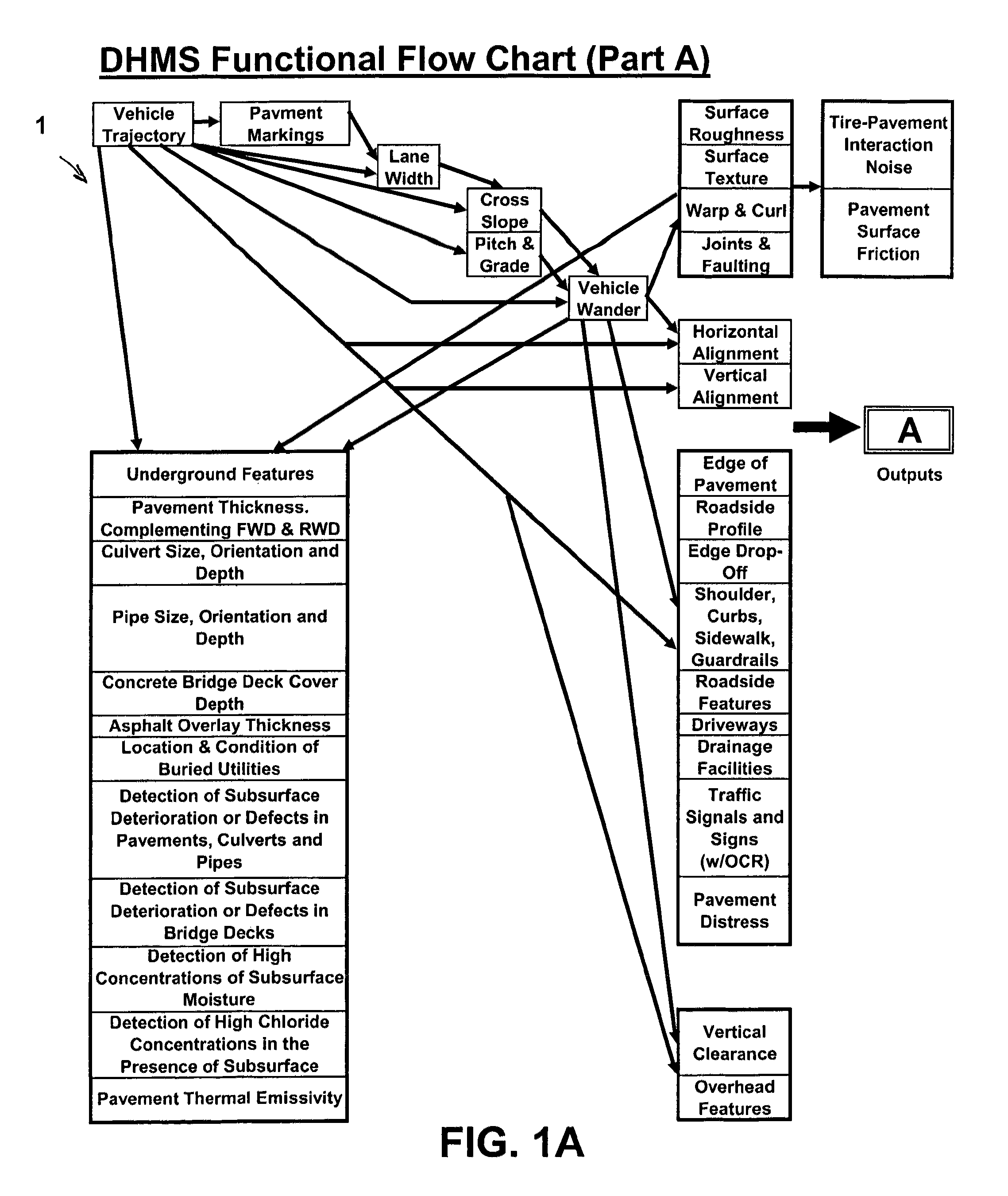
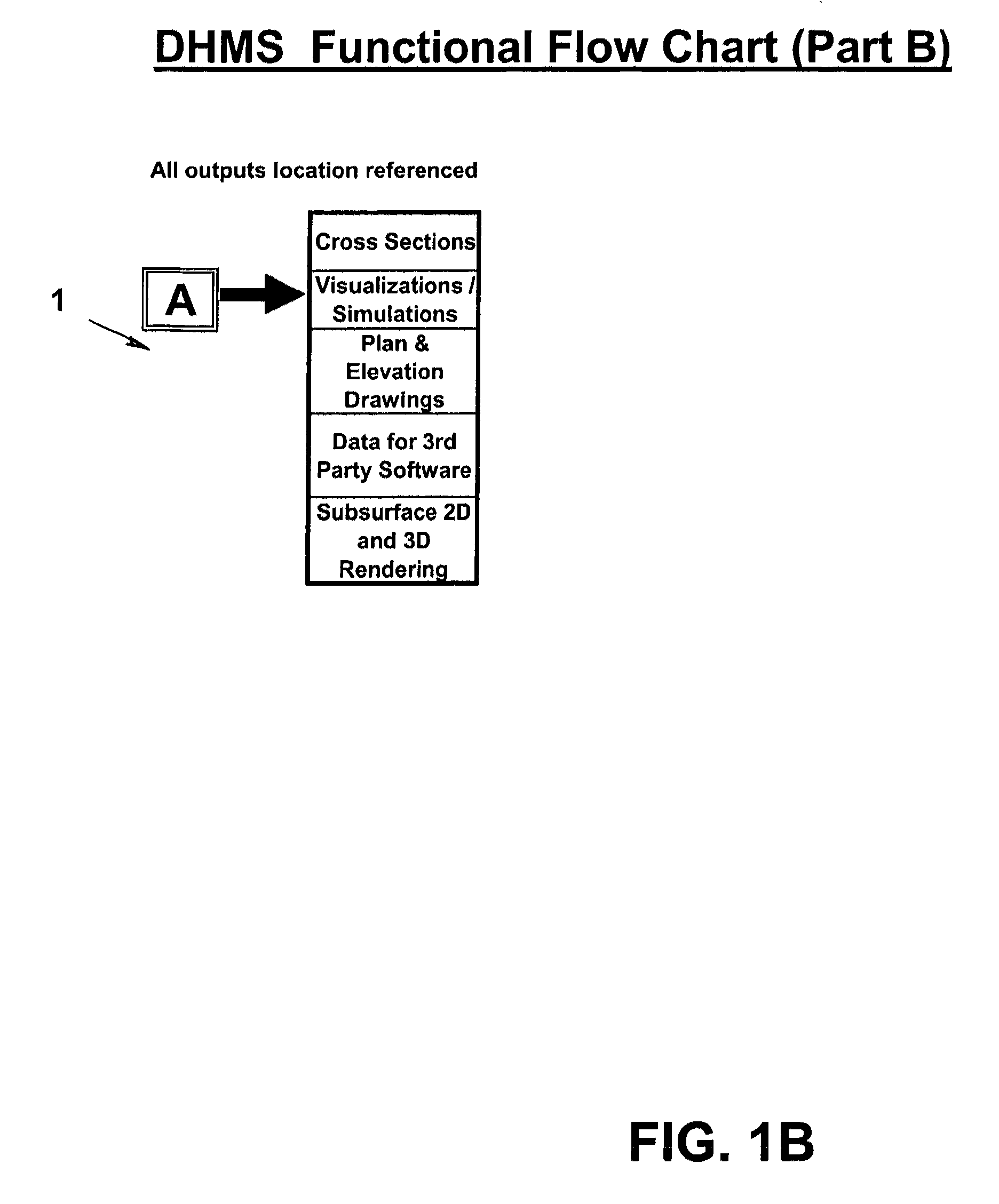
[0117]FIGS. 1A and 1B show a functional flowchart 1 of the method showing interrelationships of processing functions.

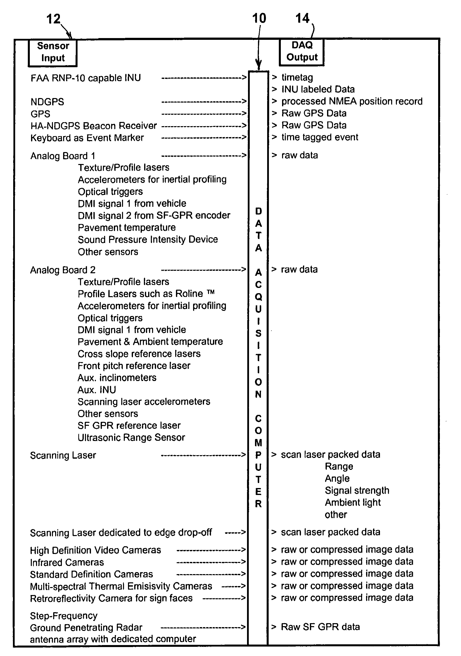
[0118]FIG. 2 shows a data acquisition computer 10 with sensor inputs 12 to the computer 10 and data outputs 14 from the computer.

[0119]FIG. 3 shows reflective laser signals 16 and 18 from lane markings to provide information of position of this vehicle in the lane of the travel way.

[0120]FIG. 4 is a graph 20 of relationships of lane width, vehicle center line, wander and coordinates.

[0121]FIG. 5 illustrates four examples 22, 24, 26, 28 of pavement edge drop offs.

[0122]FIG. 6 is a graph 30 of profile and distance relationship for measurements of faults. Data points are taken by macro texture / inertial profile sensors. Lines are generated and the difference at overlaps is the size of the fault.

[0123]FIG. 7 schematically shows GPR antenna arrays 35 with enabled 36 and disabled 37 (shaded) antennas in low speed 38 and high speed 39 operations.

[0124]FIG. 8 schematically sho...


PUM


Abstract

A mobile platform, sensors mounted on the mobile platform, computers, data storage devices, power system, data acquisition hardware, and software form a Travel Way Measurement System. The mobile platform with sensors mounted within and upon it, moves along a surface travel way and records data to determine an accurate location and geometry of the travel way surface, surface features, transverse profile and features along side the travel way surface, structures, signs, and other features above the travel way surface, and utilities, pavement thickness and properties, pavement condition, and bridge deck properties and condition below the travel way surface. The mobile platform and sensors can travel and collect data at up to 60 miles per hour or more. The data acquisition hardware and software protocols permit the synchronization of all the sensor outputs in the temporal and spatial domain or in any other domain resulting from numerical transformation of sensor outputs.

Description

[0001]This application claims the benefit of U.S. Provisional Application No. 60 / 881,526 filed Jan. 19, 2007.[0002]This invention was made with Government support under Contract DTFH61-00-C-00076 awarded by the Department of Transportation. The Government has certain rights in this invention.BACKGROUND OF THE INVENTION[0003]Engineering measurements of transportation corridors such as highways, railways, airport runways and others and complementary measurements for asset management are important to providing safe, efficient transportation. The speed, accuracy and reliability available to generate these measurements are currently inadequate to meet the evolving engineering, safety and asset management needs of federal, state, and local transportation agencies as well as other entities. Specific characteristics of the measurements required include accurate three-dimensional position referencing synchronized with accurate measurements of transportation corridor elements. A need therefor...

Claims


Application Information

Patent Timeline
IPC IPC(8): G01S13/88
CPCG01C7/04G01S15/931G01S13/885
Inventor GAGARIN, NICOLASMEKEMSON, JAMES R.SCOTT, MICHAEL L.MILLS, MILTON K.OSKARD, MORTON S.
Owner STARODUB
Why Eureka
Try Eureka