Motor drive circuit with short startup time

a technology of motor drive and startup time, which is applied in the direction of motor/generator/converter stopper, electronic commutator, dynamo-electric converter control, etc., can solve the problems of time-consuming motor start and unsuitable battery-driven electronic devices

Active Publication Date: 2012-11-13
ROHM CO LTD
View PDF13 Cites 792 Cited by
  • Summary
  • Abstract
  • Description
  • Claims
  • Application Information

AI Technical Summary

Benefits of technology

[0008]The present invention was made in view of these problems, and one general purpose thereof is the provision of motor drive technology in which the vibration motor can be started in a short time.

Problems solved by technology

The brushless motor has advantages of being small-sized and having a long life, in comparison to a brush motor, but since the rotor is heavy due to an eccentric weight, there has been a problem in that starting the motor takes time.
If it is desired to speed up the starting, methods of raising drive voltage of the motor, that is, a power supply voltage, or of switching motor impedance to increase drive current, can be considered, but since power consumption increases, these methods are not desirable in battery-driven electronic devices.

Method used


Image

  • Motor drive circuit with short startup time
  • Motor drive circuit with short startup time
  • Motor drive circuit with short startup time

Examples


first embodiment

[0051

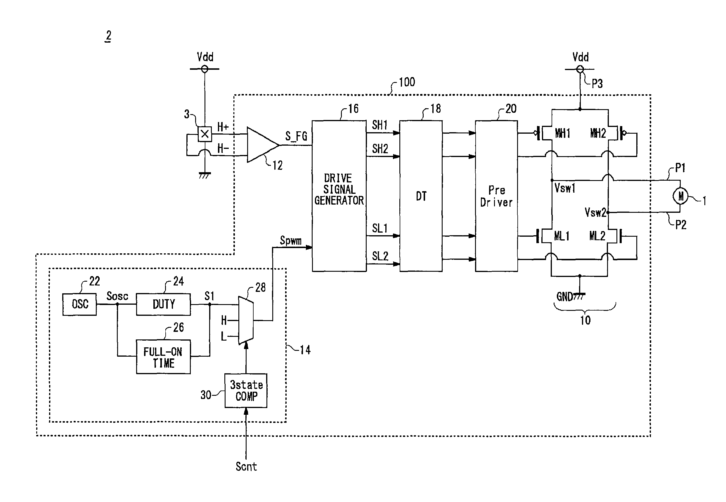
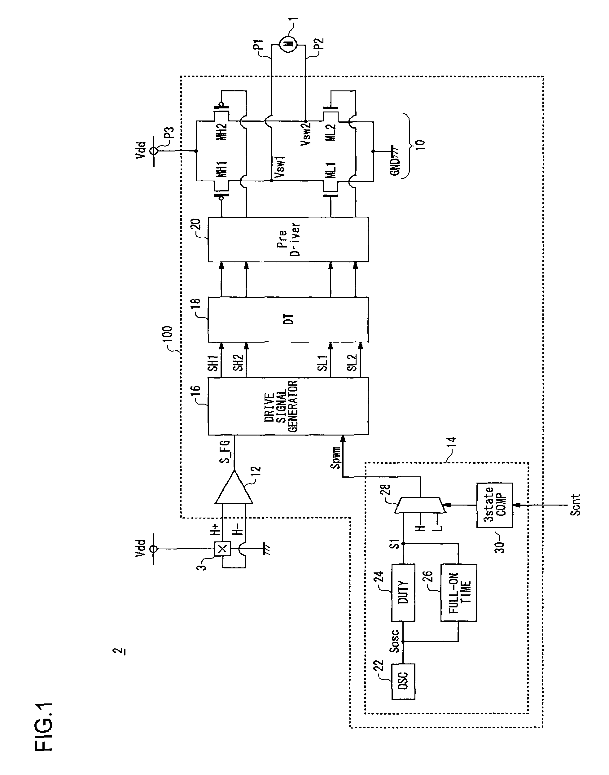
[0052]FIG. 1 is a circuit diagram showing a configuration of a motor unit 2 including the vibration motor 1 and a motor drive circuit 100 for driving the vibration motor, according to a first embodiment of the invention. The motor unit 2 is provided with the vibration motor 1, a Hall element 3, and the motor drive circuit 100, and constitutes one package.

[0053]The vibration motor 1 is a brushless motor with an attached weight that is eccentric to a rotor axis, and is formed such that voltage can be applied from outside, to both terminals P1 and P2 of a coil. The Hall element 3 outputs Hall signals H+ and H− indicating position information of the rotor of the vibration motor 1. The Hall signals H+ and H− are periodic signals with mutually opposite phases, and have a frequency according to a rotational frequency of the vibration motor 1.

[0054]The motor drive circuit 100 determines drive phase of the vibration motor 1 based on the Hall signals H+ and H− outputted from the Hall ele...

second embodiment

[0114

[0115]FIG. 5 is a circuit diagram showing a configuration of a motor unit 2 including the vibration motor 1 and a motor drive circuit 100 for driving the vibration motor, according to a second embodiment of the invention. The motor unit 2 is provided with the vibration motor 1, a Hall element 3, and the motor drive circuit 100, and constitutes one package.

[0116]The vibration motor 1 is a brushless motor with an attached weight that is eccentric to a rotor axis, and is formed such that voltage can be applied from outside, to both terminals P1 and P2 of a coil. The Hall element 3 outputs Hall signals H+ and H− indicating position information for the rotor of the vibration motor 1. The Hall signals H+ and H− are periodic signals with mutually opposite phases, and have a frequency according to a rotational frequency of the vibration motor 1.

[0117]The motor drive circuit 100 determines drive phase of the vibration motor 1 based on the Hall signals H+ and H− outputted from the Hall e...


PUM


Abstract

An H-bridge circuit is connected to a coil of the vibration motor that is to be driven. A comparator receives Hall signals indicating position information of a rotor of the vibration motor, and converts to an FG signal. A pulse width modulator generates a pulse-modulated pulse signal specifying energization time of the coil of the vibration motor. The pulse width modulator, in a first mode, after commencing start-up of the vibration motor, sets a duty ratio of the pulse signal to 100%, and after that, switches the duty ratio to a predetermined value in accordance with rotational frequency of the motor. In a second mode, the duty ratio of the pulse signal continues to be set to 100%. In a third mode, frequency and the duty ratio of the pulse signal are set based on a control signal of a pulse form inputted from outside. The control signal is used also in switching mode.

Description

CROSS REFERENCE TO RELATED APPLICATIONS[0001]This is a U.S. national stage of application No. PCT / JP2007 / 000929, filed on 29 Aug. 2007. Priority under 35 U.S.C. §119(a) and 35 U.S.C. §365(b) is claimed from Japanese Application No. 2006-234208, filed 30 Aug. 2006, and Japanese Application No. 2006-242040, filed 6 Sep. 2006, the disclosure of which is also incorporated herein by reference.FIELD OF THE INVENTION[0002]The present invention relates to motor drive technology.DESCRIPTION OF THE RELATED ART[0003]In electronic devices such as mobile telephones, pagers, and the like, a vibration motor is installed to notify a user of an incoming message. In this vibration motor, by connecting a weight that is eccentric to a rotational axis and rotating a rotor, the electronic device is made to vibrate. In such a vibration motor, since the weight, which is connected as a load, is eccentric, a drive circuit dedicated to the vibration motor (referred to below as simply a vibration motor drive c...

Claims


Application Information

Patent Timeline
Patent Type & Authority Patents(United States)
IPC IPC(8): H02P6/00H02P6/08H02P6/06H02P6/26
CPCH02P6/085H02P6/14H02P6/20Y10S388/9072
Inventor NAKAI, TATSUJI
Owner ROHM CO LTD
Why Eureka
Try Eureka