Surface gap soot sensor for exhaust

a soot sensor and surface gap technology, applied in the direction of instruments, electrical control, combustion types, etc., can solve the problems of engine thermal efficiency decline, exhaust gases experience a significant pressure drop passing through the increasingly restrictive filter, and problems such as problems, to achieve the effect of preventing current flow

a soot sensor and surface gap technology, applied in the direction of instruments, electrical control, combustion types, etc., can solve the problems of engine thermal efficiency decline, exhaust gases experience a significant pressure drop passing through the increasingly restrictive filter, and problems such as problems, to achieve the effect of preventing current flow

US8310249B2Active Publication Date: 2012-11-13WOODWARD GOVERNOR CO

Image

  • Surface gap soot sensor for exhaust
  • Surface gap soot sensor for exhaust
  • Surface gap soot sensor for exhaust

Examples


Embodiment Construction

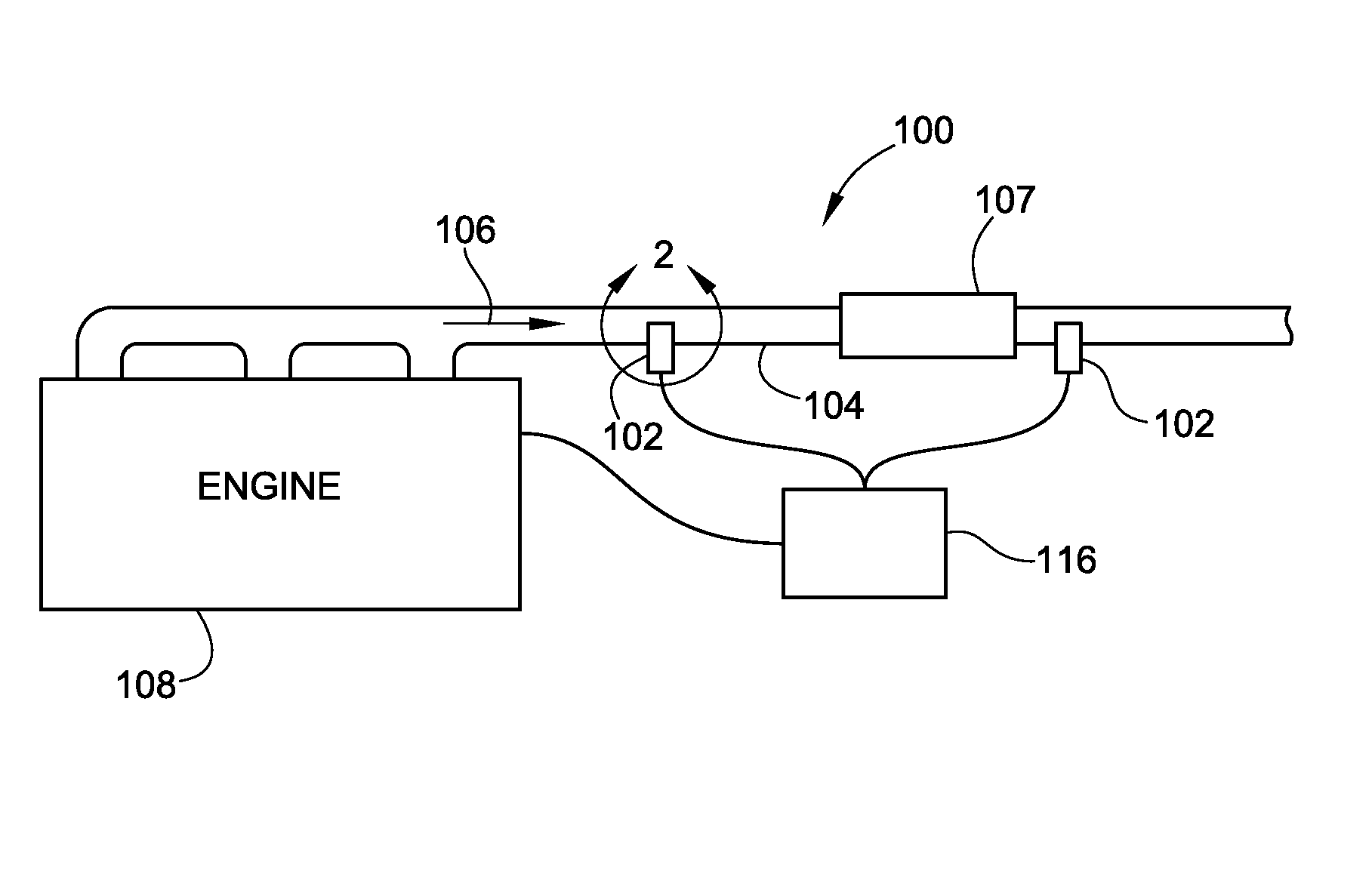
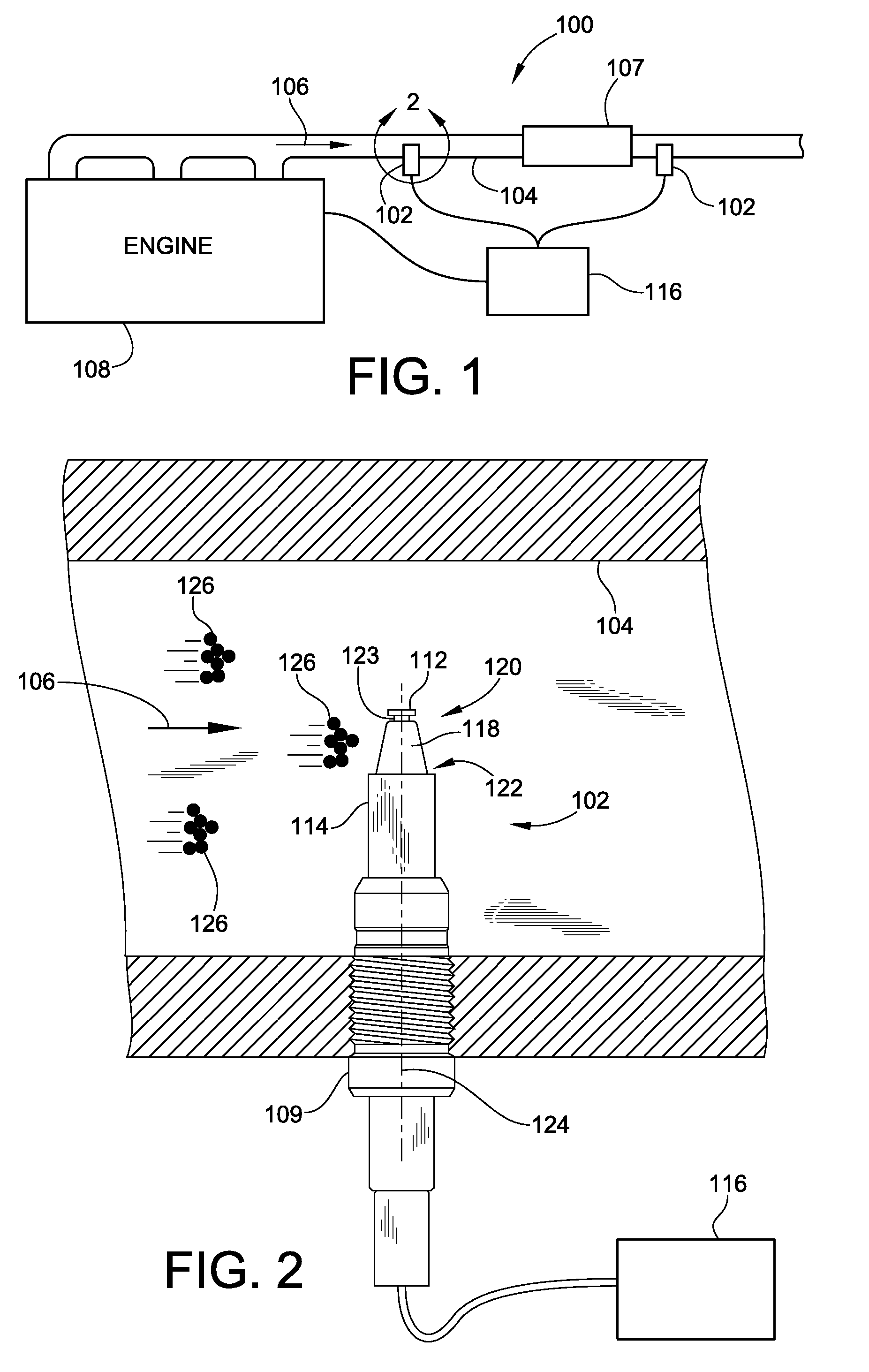
[0040]FIG. 1 is a simplified schematic representation of an embodiment of a particulate sensor arrangement 100 (also referred to herein as a “soot sensor arrangement 100”) according to the teachings of the present invention. As used here in “particulates,”“particles,” and “soot” are generally synonymous for purposes of understanding the embodiments of the present invention. The soot sensor arrangement 100 includes a sensor 102 mounted within an exhaust pipe 104. Exhaust 106 (illustrated as arrow 106) flowing through the exhaust pipe 104 generated by engine 108 impinges on the sensor 102 and the sensor provides feedback as to the concentration of particulate matter within the exhaust flow 106. While the sensor is illustrated in an exhaust pipe 104, the sensor 102 could be used in other locations along the exhaust flow path, such as within the exhaust manifold, downstream of any boost device or downstream from a DPF 107.

[0041]As illustrated in FIG. 1, a plurality of sensors 102 may be...


PUM


Abstract

A method and apparatus for sensing particulates within an exhaust flow are provided. The methods and apparatus utilize a soot sensor that includes opposed electrodes separated by an insulator. Preferably, a gap is formed between the electrodes and the insulator to prevent electrical current from flowing therebetween. The soot sensor, when positioned in an exhaust flow, will accumulate a layer of particulates on an outer surface thereof. As the layer of particulates increases the particulates will bridge the two electrodes permitting current flow. The sensor is configured with a proper geometry and potential difference between the electrodes to generate currents in the milli-amp range. Further, the sensor is configured to have a regenerative effect that causes the bridge to be broken when particles sees to impinge the soot sensor.

Description

FIELD OF THE INVENTION[0001]This invention generally relates to engine exhaust systems and more particularly systems and methods for sensing particulate matter generation within an exhaust system.BACKGROUND OF THE INVENTION[0002]Increasing environmental restrictions and regulations are causing diesel engine manufacturers and packagers to develop technologies that improve and reduce the impact that operation of such engines have on the environment. As a result, much design work has gone into the controls that operate the combustion process within the engine itself in an attempt to increase fuel economy and reduce emissions such as NOx and particulate matter (e.g. soot). However, given the operating variables and parameters over which a diesel engine operates and given the tradeoff between NOx and particulate generation, many engine manufacturers and packagers have found it useful or necessary to apply exhaust after-treatment devices to their systems. These devices are used to filter ...

Claims


Application Information

Patent Timeline
13 Nov 2012
Publication
US8310249B2
IPC
G01R27/08
CPC
F02D41/1466; G01N15/0656
Inventors
PATERSON, CLARK