Air filter assembly for combustion tool

a technology of air filter and combustion tool, which is applied in the direction of filtration separation, auxillary pretreatment, separation process, etc., can solve the problems of insufficient deflection opportunity for contaminating particulates, insufficient directional change of airflow, and too thin, so as to reduce the number of instances of clogging, increase the pore size, and reduce the amount of clogging

Inactive Publication Date: 2012-11-20
ILLINOIS TOOL WORKS INC
View PDF48 Cites 7 Cited by
  • Summary
  • Abstract
  • Description
  • Claims
  • Application Information

AI Technical Summary

Benefits of technology

[0010]The present filter assembly addresses the above-identified drawbacks of conventional combustion tool air filters and features a foam filter that has pores larger than the target particle size, and is preferably saturated with oil. It has been found that the larger pore size allows ample airflow, decrease instances of clogging, increases particle path distance, the number of directional changes, and the number of deflection opportunities within the filter element and the filter housing assembly. Additionally, the oil that saturates the foam filter traps ten-micron particulates. Such an assembly has proved to increase tool life by at least three times, provide high filtration without air flow degradation, and reduce the cost of filter material. Tools having the present filter assembly are cleaner, thereby decreasing friction and allowing the engine to run cooler. The internal moving parts in the o-ring areas also stay clean and do not bind, thus eliminating the user hitting the tool hard against the substrate to force actuation among dirty binding parts. Furthermore, oil vapor from the oil saturated filter can travel from the filter into the cylinder and piston assembly of the tool thus reducing friction, o-ring wear, and the drying out of O-rings.

Problems solved by technology

An unfortunate side effect of working in such environments is that unwanted contaminating particles regularly gum up and jam the moving parts of the tool and make it inoperable relatively early in its life cycle.
Although foam filters provide ample airflow, they are often too thin and do not allow for sufficient directional changes of airflow.
Consequently, deflection opportunities for contaminating particulates are often insufficient.
Moreover, the pores in these filters are too large and often do not trap tiny particulates of ten microns or less.
These filters, however, clog quickly, restrict airflow, and inhibit combustion tool operation.
Sponge filters allow contamination to pass into the internal parts of the engine and cause premature failure.
Pleated filters are relatively expensive compared to foam and sponge filters and also require frequent replacement.

Method used


Image

  • Air filter assembly for combustion tool
  • Air filter assembly for combustion tool
  • Air filter assembly for combustion tool

Examples


Embodiment Construction

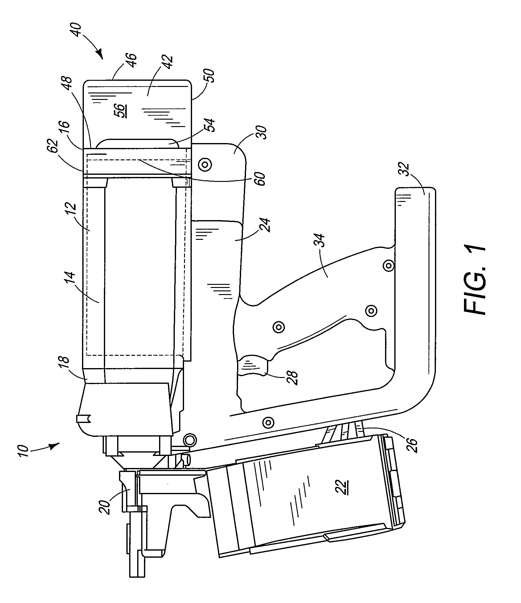
[0021]Referring now to FIG. 1, a combustion tool suitable for use with the present filter assembly is generally designated 10. It will be appreciated that the specific type and configuration of combustion tool may vary to suit the application. Included in the tool 10 is a tool housing 12 enclosing a combustion power source 14 (shown hidden) and having an upper housing or air intake end 16 and an opposite fastener driving end 18. Projecting from the fastener driving end. 18 is a tool nosepiece 20. Fasteners are fed from a magazine 22 into the nosepiece 20, where they are impacted by a driver blade (not shown) reciprocating within the power source 14 as well known in the art. The magazine 22 is shown as a coil type, however straight magazines using strips of fasteners are also contemplated.

[0022]A handle portion 24 of the housing 12 supports the magazine 22 by providing an attachment point 26. Also found on the handle portion 24 is a trigger 28 for initiating the combustion that drive...


PUM

PropertyMeasurementUnit
pore sizeaaaaaaaaaa
particle sizeaaaaaaaaaa
thicknessaaaaaaaaaa

Abstract

A filter element for a combustion tool includes a filter medium having pores with a pore size greater than a target particle size.

Description

BACKGROUND[0001]The present invention relates to power tools, and more specifically to air filters used in combustion gas-powered tools.[0002]In the construction industry, when power tools are used in the field, on construction sites and in remote areas, tools having a self-contained source of power are preferred. One example of a self-contained source of power is a combustion engine housed within a tool. Such tools are known as combustion-powered tools or combustion tools.[0003]Combustion tools are known in the art, and are described in U.S. Pat. Re. No. 32,452, and U.S. Pat. Nos. 4,522,162; 4,483,473; 4,483,474; 4,403,722; 5,197,646; 5,263,439 and 6,145,724, all of which are incorporated by reference herein. Similar combustion-powered nail and staple driving tools are available commercially from Illinois Tool Works of Glenview, Ill.[0004]Such tools incorporate a tool housing enclosing a small internal combustion engine. The engine is powered by a canister of pressurized fuel gas, ...

Claims


Application Information

Patent Timeline
Patent Type & Authority Patents(United States)
IPC IPC(8): B01D46/00
CPCB01D46/0035B01D46/106B25C1/08B25F5/008B01D2275/30B01D2275/403B01D2279/60
Inventor PANASIK, CHERYL L.TUCKER, KEVIN M.
Owner ILLINOIS TOOL WORKS INC
Why Eureka
Try Eureka