Multi color active regions for white light emitting diode
Active Publication Date: 2012-11-20
SLT TECH
View PDF112 Cites 247 Cited by
Summary
Abstract
Description
Claims
Application Information
AI Technical Summary
This helps you quickly interpret patents by identifying the three key elements:
Problems solved by technology
Method used
Benefits of technology
[0011]One or more benefits may be achieved using one or more of the specific embodiments. As an example, the present device and method provides for an improved lighting technique with improved efficiencies. In other embodiments, the present method and resulting structure are easier to implement using conventional technologies. In some embodiments, the present device and method provide light at two or more wavelengths that are useful in displays. In a specific embodiment, the blue LED device is cap
Problems solved by technology
Unfortunately, one drawback with the conventional Edison light bulb is that it dissipates much of the electricity supplied to it as thermal energy.
Additionally, the conventional light bulb routinely fails often due to thermal expansion and contraction of the filament element.
Unfortunately, achieving high intensity, high-efficiency GaN-based green LEDs has been particularly problematic.
The performance of optoelectronic devices fabricated on conventional c-plane GaN suffer from strong internal polarization fields, which spatially separate the electron and hole wave functions and lead to poor radiative recombination efficiency.
Since this phenomenon becomes more pronounced in InGaN layers with increased indium content for increased wavelength emission, e
Method used
Image
Click on the blue label to locate the original text in one second.
Reading with bidirectional positioning of images and text.
Examples
Example
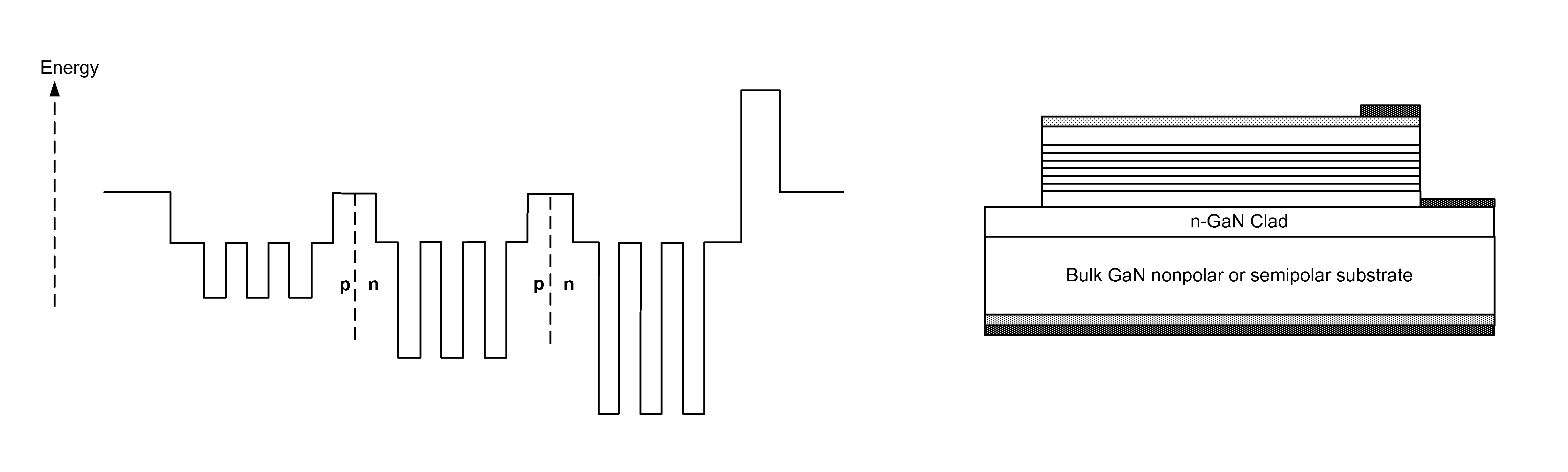
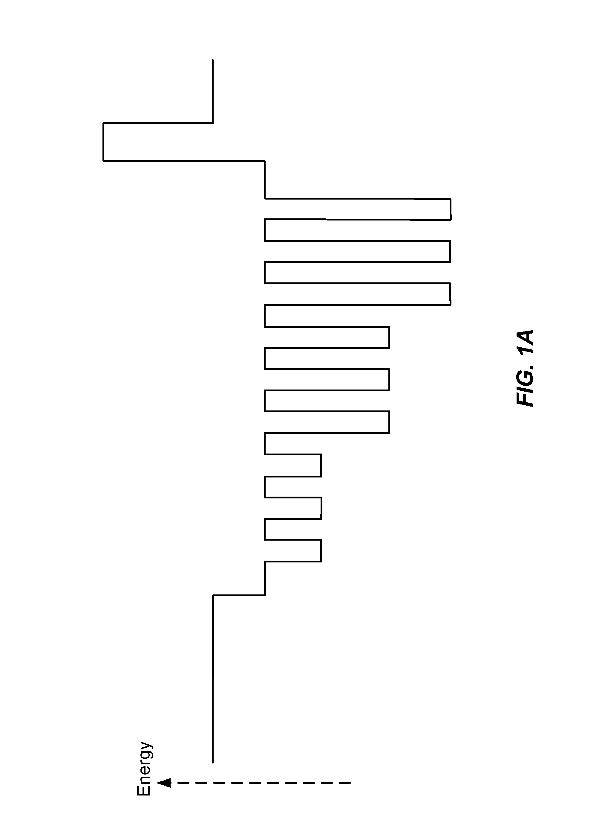
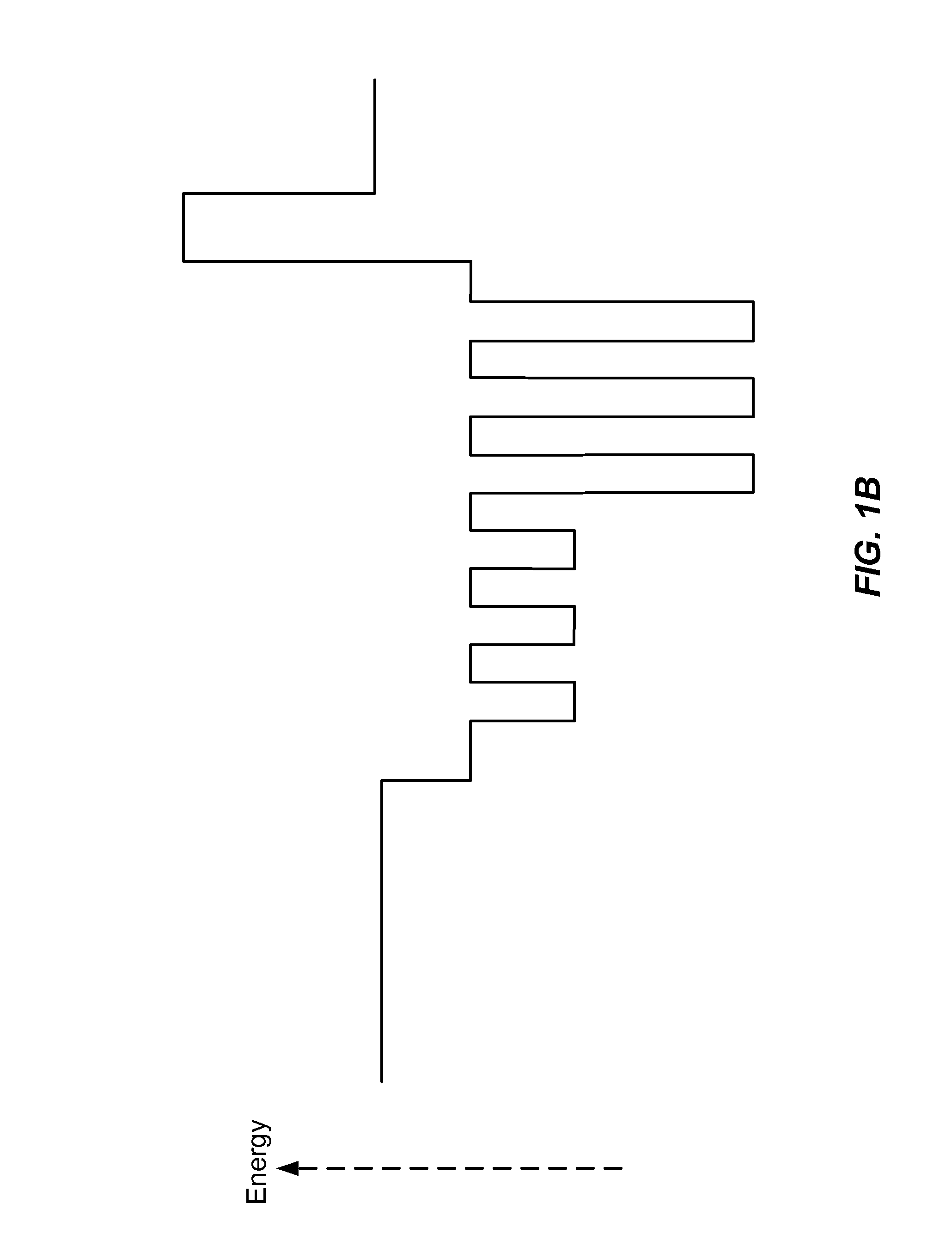
[0021]In a specific embodiment, the present invention includes a single growth epitaxial structure containing active layers that emit red, green, and blue radiation, or red, green, yellow, and blue radiation, or blue and yellow radiation from the same layer stack resulting in white light emission. The epitaxial structure is fabricated into an LED that emits white light without the need for a phosphor. See, for example, FIGS. 1A, 1B, and 1C and FIGS. 2A and 2B.
[0022]In a specific embodiment, the light emitting layers are formed from InGaN in which the indium content dictates the emission wavelength. The InGaN light emitting layers may be quantum wells separated by quantum barriers or may be double hetereostructures type emitting layers.
[0023]The emitting layers can be contained within the same p-i-n junction such that adjacent layers can be emitting different colors. Such a configuration would lead to an ideal diode turn-on voltage equal to the largest bandgap of the emitting layers....
PUM
Abstract
A light emitting diode device has a gallium and nitrogen containing substrate with a surface region with an epitaxial layer overlying the surface region. Preferably the device includes a first active region overlying the surface and configured to emit first electromagnetic radiation having a wavelength ranging from about 405 nm to 490 nm; a second active region overlying the surface and configured to emit second electromagnetic radiation having a wavelength ranging from about 491 nm to about 590 nm; and a third region overlying the surface region and configured to emit third electromagnetic radiation having a wavelength ranging from about 591 nm to about 700 nm. A p-type epitaxial layer covers the first, second, and third active regions.
Description
CROSS-REFERENCE TO RELATED APPLICATION[0001]This application claims priority to U.S. Provisional Patent Application No. 61 / 242,372, filed Sep. 14, 2009, which is incorporated by reference herein for all purposes.BACKGROUND OF THE INVENTION[0002]This invention relates generally to lighting techniques. More specifically, embodiments of the invention include techniques for combining one or more colored LED devices, such as violet, blue, blue and yellow, or blue and green, fabricated on semipolar or nonpolar materials, and optionally, with use of entities such as phosphors, which emit light. The invention can be applied to applications such as white lighting, multi-colored lighting, general illumination, decorative lighting, automotive and aircraft lamps, street lights, lighting for plant growth, indicator lights, lighting for flat panel displays, other optoelectronic devices, and the like.[0003]In the late 1800's, Thomas Edison invented the light bulb. The conventional light bulb, comm...
Claims
Application Information
Patent Timeline
Application Date:The date an application was filed.
Publication Date:The date a patent or application was officially published.
First Publication Date:The earliest publication date of a patent with the same application number.
Issue Date:Publication date of the patent grant document.
PCT Entry Date:The Entry date of PCT National Phase.
Estimated Expiry Date:The statutory expiry date of a patent right according to the Patent Law, and it is the longest term of protection that the patent right can achieve without the termination of the patent right due to other reasons(Term extension factor has been taken into account ).
Invalid Date:Actual expiry date is based on effective date or publication date of legal transaction data of invalid patent.