Integration of LNG regasification with refinery and power generation

a technology of lng regasification and power generation, applied in the direction of machines/engines, machine/engine discharging methods, lighting and heating apparatus, etc., can solve the problems of environmental impact in either scenario, lng regasification is remarkably energy intensive process, and most conventional lng regasification processes are energy inefficient or often environmentally problemati

Inactive Publication Date: 2012-11-27
FLUOR TECH CORP
View PDF23 Cites 82 Cited by
  • Summary
  • Abstract
  • Description
  • Claims
  • Application Information

AI Technical Summary

Problems solved by technology

While natural gas has become an economically attractive commodity, liquefaction and regasification are remarkably energy intensive processes.
Unfortunately, the ecologic impact in either scenario, and especially over prolonged periods is significant.
Thus, most conventional LNG regasification processes are energy inefficient or often environmentally problematic.
Indeed, there are potentially significant synergies between power generation and LNG regasification.
However, such LNG regasification processes rely on the heat content in the gas turbine intake air for LNG heating that may not be available during winter months, especially in colder climates.
Therefore, additional heating with conventional methods is often necessary.
Thus, while all or almost all of such improved configurations and methods provide at least some advantages over previously known configurations, various disadvantages still remain.
Among other things, most of the known methods fail to provide continuous sources of heating for LNG regasification, and therefore rely on supplementary heating.

Method used


Image

  • Integration of LNG regasification with refinery and power generation
  • Integration of LNG regasification with refinery and power generation
  • Integration of LNG regasification with refinery and power generation

Examples


Embodiment Construction

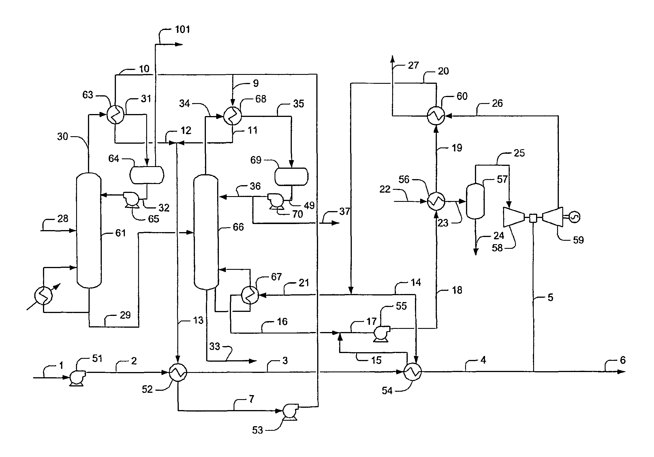
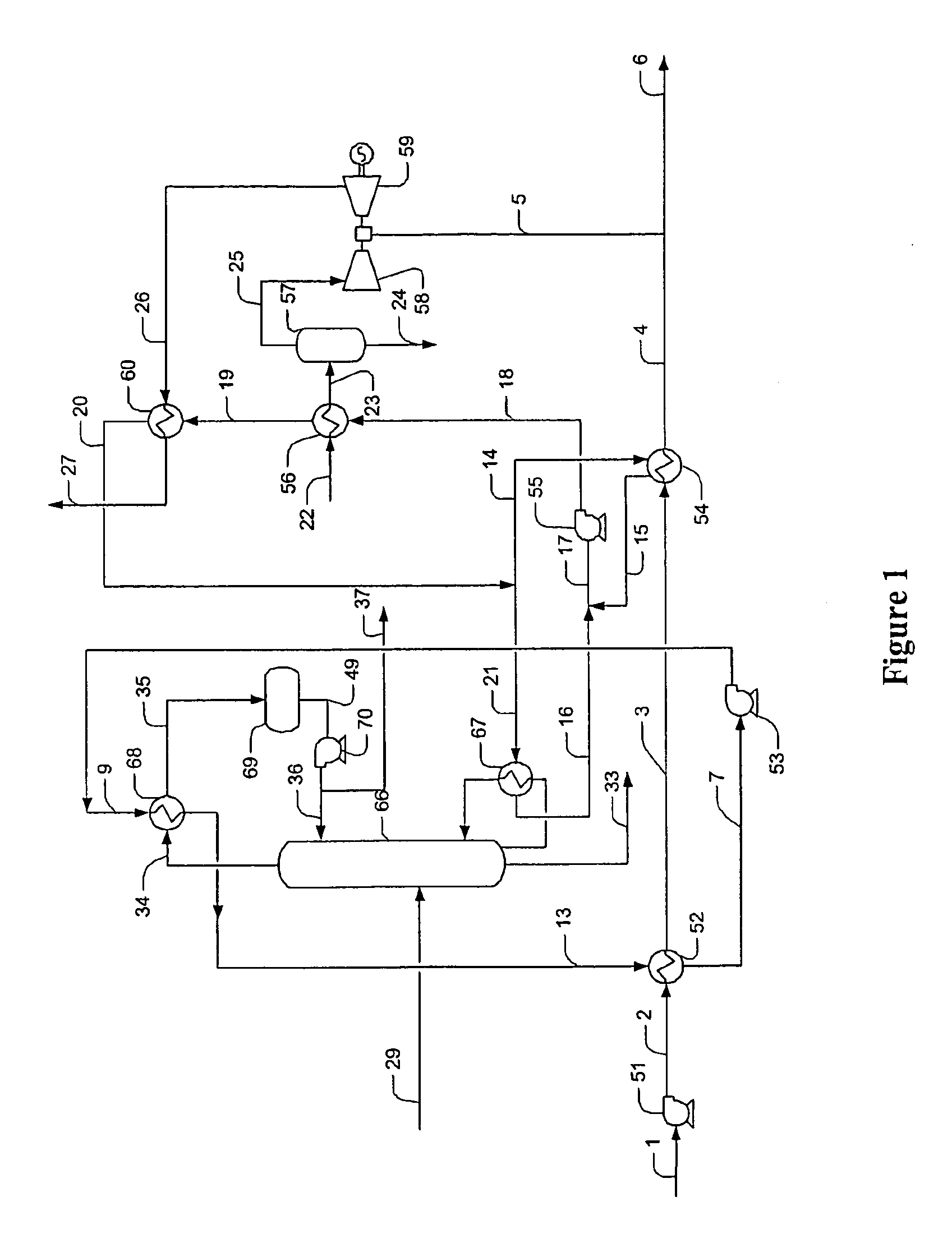
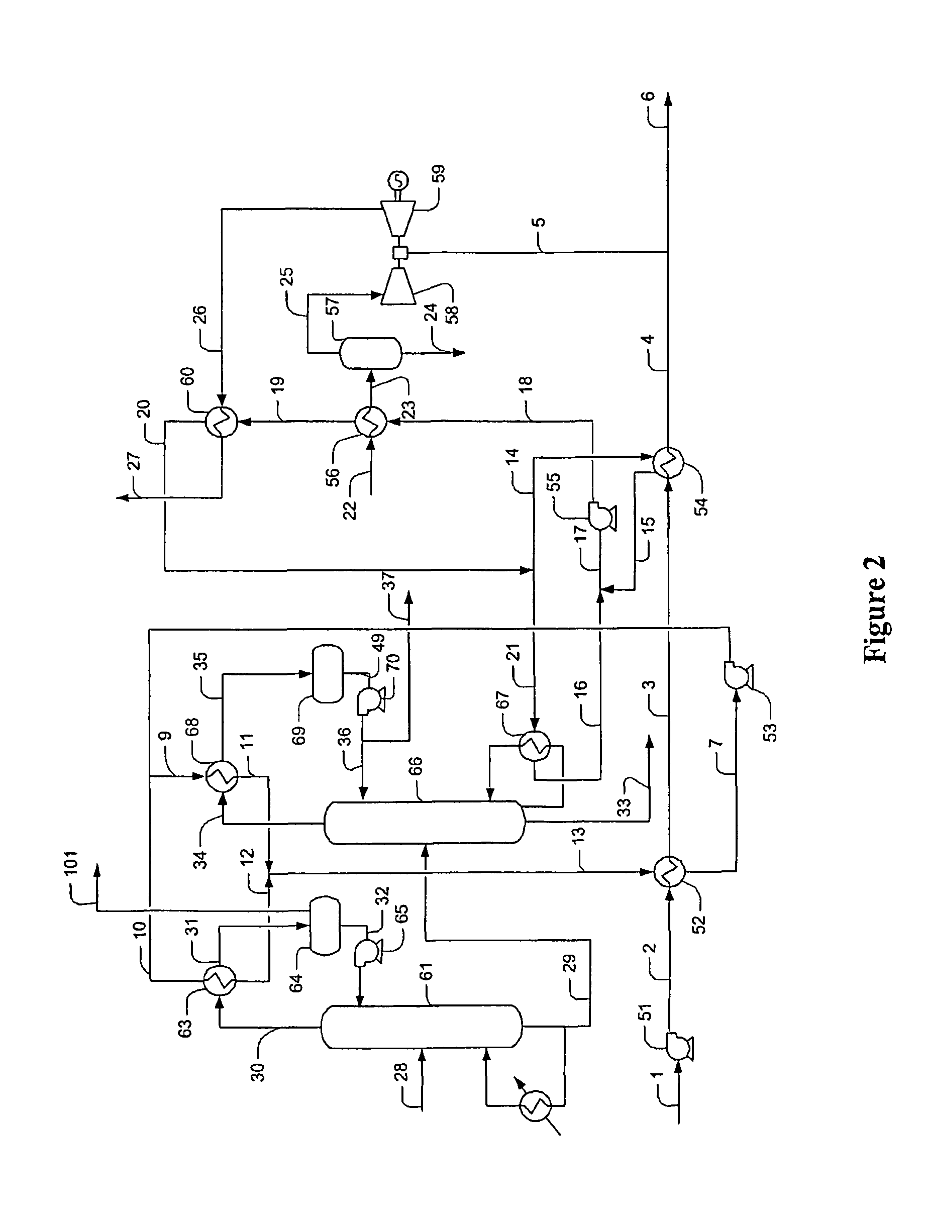
[0016]The inventor discovered that LNG can be regasified in a plant configuration in which one or more refinery processes and / or power generation schemes provide a continuous heat source for regasification. Most preferably, LNG regasification is achieved using at least two heating stages, wherein the first heating stage employs a heat transfer fluid that is thermally coupled with a refinery component (and especially an overhead condenser), and wherein the second heat stage employs another heat transfer fluid that is thermally coupled with a power generation component (and especially an intake air chiller and / or flue gas exchanger).

[0017]For example, in one preferred aspect, a regasification terminal is thermally coupled to a hydrocarbon splitter, and especially a C3 splitter in a refinery to produce C3 (propane) and C3= (propylene) products, while the C3 splitter generates refrigerant for chilling gas turbine inlet air for power production. Additionally, LNG regasification can be fu...


PUM


Abstract

Contemplated plants thermally integrate operation of a refinery component, and most preferably of a hydrocarbon splitter with LNG regasification to provide refrigeration duty and with a power cycle to provide the reboiler duty of the component. It should be noted that such configurations advantageously allow operation of the splitter at a reduced temperature and at reduced pressure, thereby increasing separation efficiency, while the power output is boosted using air intake chilling. Most notably, such process advantages are achieved by satisfying the heating duty of LNG regasification.

Description

[0001]This application claims priority to our U.S. provisional patent application with the Ser. No. 60 / 667,002, which was filed Mar. 30, 2005.FIELD OF THE INVENTION[0002]The field of the invention is LNG regasification and utilization, and especially use of LNG (liquefied natural gas) cold from regasification in processing plants and power generation plants.BACKGROUND OF THE INVENTION[0003]While natural gas has become an economically attractive commodity, liquefaction and regasification are remarkably energy intensive processes. In many instances, liquefaction of natural gas requires about 230 kW for each MMscfd of high-pressure natural gas, which corresponds to about 280 MW of power in a 1,200 MMscfd liquefaction plant. On the other hand, regasification of 1,200 MMscfd LNG requires about 750 MM Btu / hr of heating duty.[0004]Most typically, heating duty is supplied by heat exchange with seawater cooling about 100,000 gpm of seawater by 15° F., or using combustion heat from 20 MMscfd ...

Claims


Application Information

Patent Timeline
Patent Type & Authority Patents(United States)
IPC IPC(8): F25J3/00
CPCF25J3/0219F25J3/0238F25J3/0242F17C2221/033F17C2223/0161F17C2223/033F17C2225/0123F17C2225/035F17C2227/0135F17C2227/0323F17C2227/0332F17C2227/0393F17C2265/015F17C2265/05F17C2270/0136F25J2210/12F25J2210/62F25J2215/62F25J2215/64F25J2270/904Y02E20/16
Inventor MAK, JOHN
Owner FLUOR TECH CORP
Why Eureka
Try Eureka