MEMS-based micro and nano grippers with two-axis force sensors

a micro and nano technology, applied in the field of micro and nanosystems, micro and nanotechnology, can solve the problems of microgripper breakage, microgripper breakage, and existing microgrippers without force feedback

Active Publication Date: 2012-11-27
SUN YU +1
View PDF12 Cites 14 Cited by
  • Summary
  • Abstract
  • Description
  • Claims
  • Application Information

AI Technical Summary

Benefits of technology

[0010]In an embodiment of the present invention, integrated, single-chip, batch microfabricated MEMS devices are disclosed that are electrothermally-driven microgrippers with integrated dual-axis force sensing capabilities. The gripping motion is produced by an actuator, such as a bent-beam actuator. The bent-beam actuator requires little power and is capable of producing a large range of gripping forces and displacements. Integrated force sensors along the in-plane x and y directions using transverse differential capacitive comb drives enable the measurement of gripping forces as well as the forces applied at the end of microgripper arms along the normal direction, both with a resolution down to nanoNewton.
[0012]This microgripper design features two-axis force sensing capabilities suitable for use in intelligent micro and nanomanipulation. Additionally, the employment of bent-beam electrothermal microactuators permits the grasping of objects of a large range of sizes.

Problems solved by technology

The lack of force feedback at the microNewton and nanoNewton level severely limits intelligent micro- and nanomanipulation.
The vast majority of existing microgrippers lack force feedback due to the difficulty of integrating force sensors with microgrippers.
The lack of force feedback does not permit force-controlled manipulation and easily causes breakage of microgrippers and damage to the object to be manipulated.
However, the gripping force sensing resolution is somewhat poor, on the order of milli-Newton that is orders of magnitude worse than what micro-nanomanipulation requires.
Due to the limitation of electrostatic actuation (low force output, small displacements, and high driving voltage), the microgripper design is only capable of grasping objects of a small range of sizes.
The lack of force sensing capabilities along a second-axis down to nanoNewton in existing designs does not allow for the protection of microgrippers and the detection of contact between the microgripper and object to be manipulated.

Method used


Image

  • MEMS-based micro and nano grippers with two-axis force sensors
  • MEMS-based micro and nano grippers with two-axis force sensors
  • MEMS-based micro and nano grippers with two-axis force sensors

Examples


Embodiment Construction

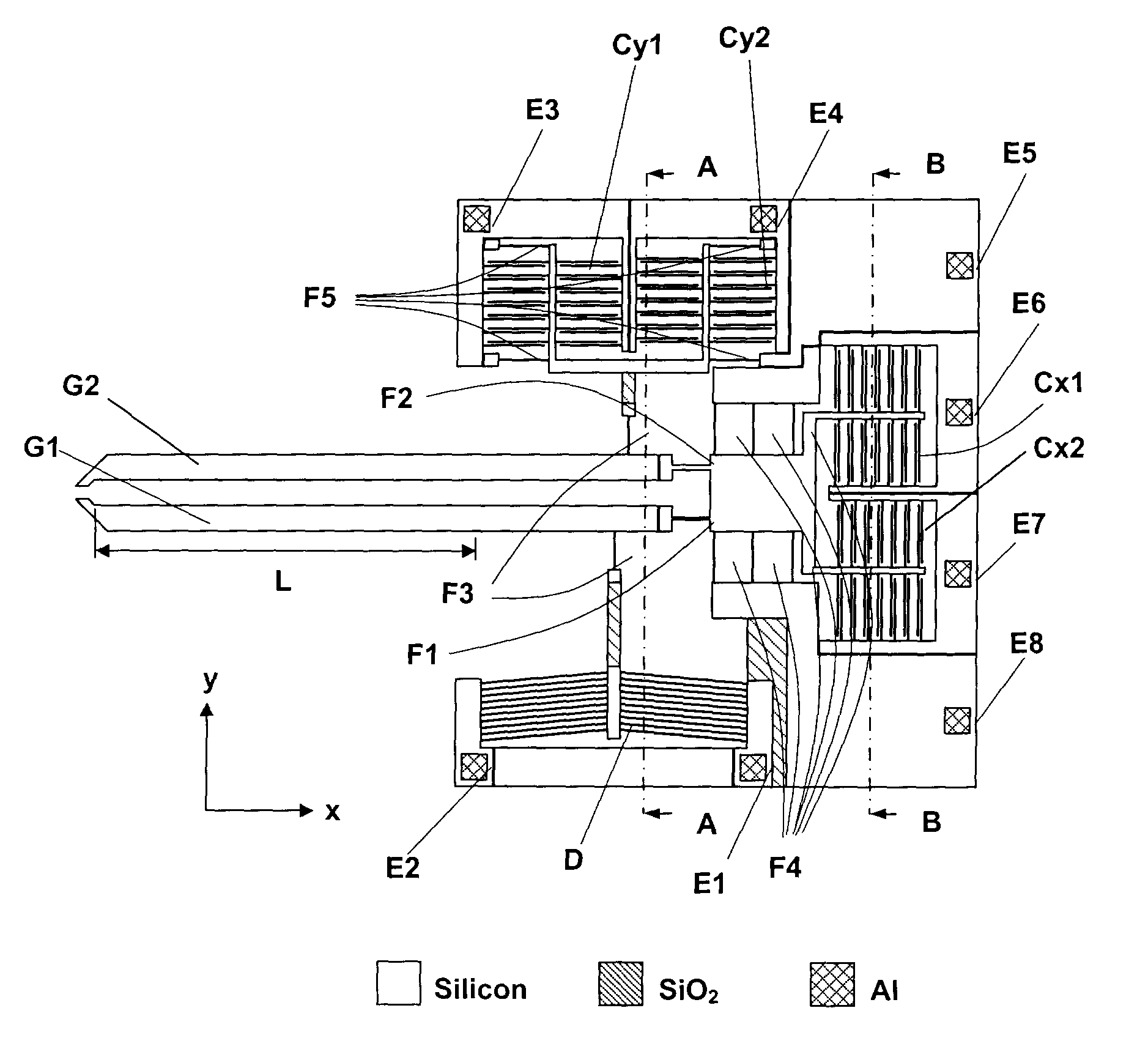
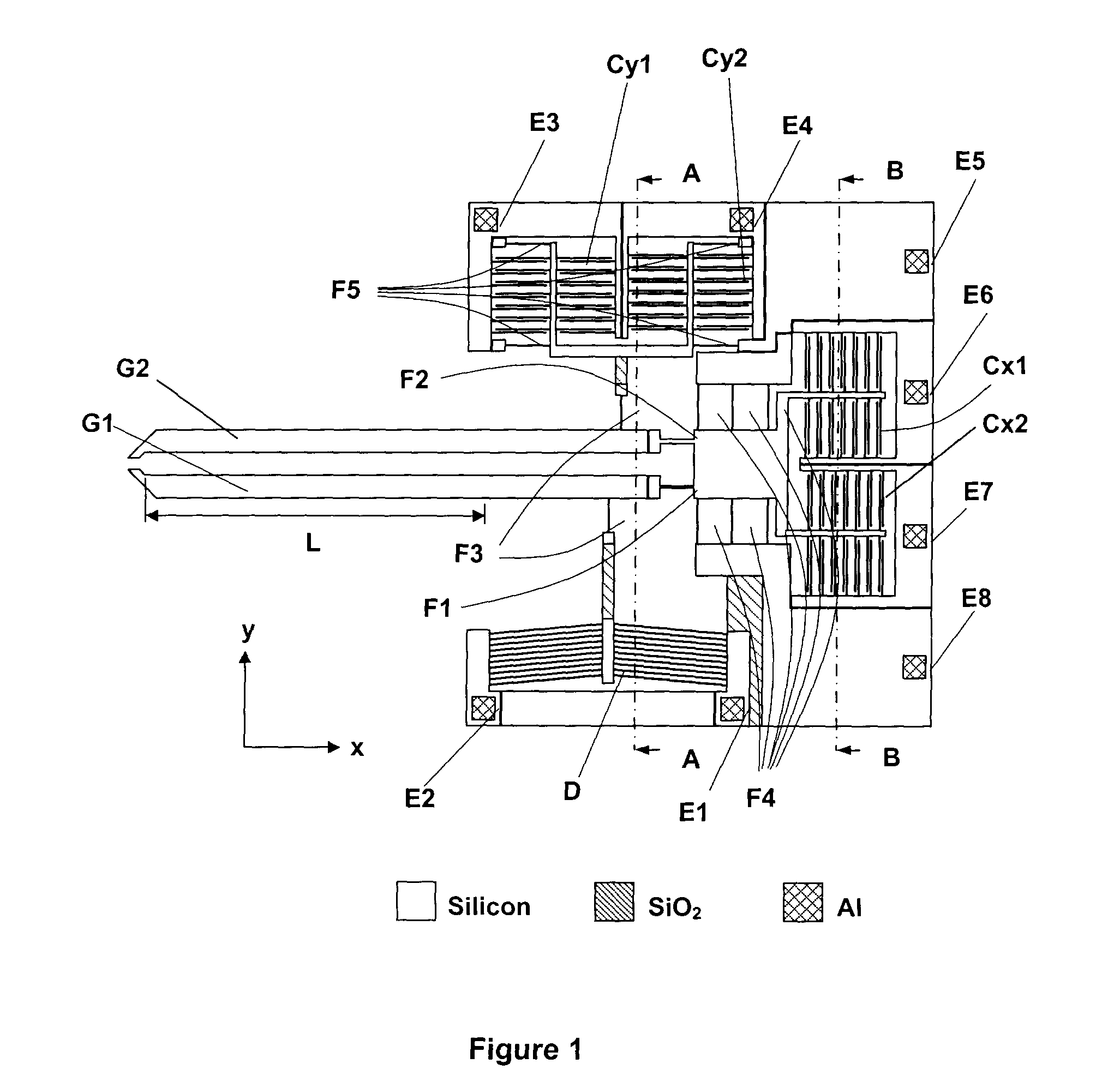
[0019]In an embodiment of the present invention, an electrothermally actuated microgripper comprises four parts, as illustrated in FIG. 1: (i) electrothermal microactuator D to drive gripper arm G1; (ii) driving arm G1 and sensing arm G2 used together to grasp micro / nano objects; (iii) linear beam flexures F1, F2, F3, F4, and F5 used to transform forces into displacements; and (iv) pairs of capacitor plates forming capacitors Cx1, Cx2, Cy1, and Cy2 to transform displacements into capacitance changes.

[0020]In this case, the electrothermal microactuator D is a bent-beam microactuator. However, it should be understood that other types of electrothermal actuators are possible and within the scope of the present invention, such as U-beam electrothermal actuators or electrostatic actuators, for example. It should also be understood that piezoresistive force sensors could be used instead of capacitive force sensors.

[0021]Electrothermal bent-beam microactuator D produces forces to deflect t...


PUM

PropertyMeasurementUnit
lengthaaaaaaaaaa
thickaaaaaaaaaa
thickaaaaaaaaaa

Abstract

The present invention relates to a design and microfabrication method for microgrippers that are capable of grasping micro and nano objects of a large range of sizes and two-axis force sensing capabilities. Gripping motion is produced by one or more electrothermal actuators. Integrated force sensors along x and y directions enable the measurement of gripping forces as well as the forces applied at the end of microgripper arms along the normal direction, both with a resolution down to nanoNewton. The microfabrication method enables monolithic integration of the actuators and the force sensors.

Description

PRIORITY[0001]This application claims the benefit of Canadian Patent No. 2,551,191, filed 23 Jun. 2006.FIELD OF THE INVENTION[0002]The present invention relates to micro and nanosystems, and micro and nanotechnology.BACKGROUND OF THE INVENTION[0003]Intelligent manipulation (e.g., grasping / gripping) of micro- and nanometer-sized objects requires the use of miniaturized microgrippers with integrated force sensors. Currently, micro- and nanomanipulation typically relies purely on visual feedback either from an optical microscope or an electron microscope. The lack of force feedback at the microNewton and nanoNewton level severely limits intelligent micro- and nanomanipulation.[0004]Besides miniaturization and electrical control, microgrippers must be capable of providing multi-axis force feedback to satisfy the following requirements: (i) to protect the microgripper and detect the contact between the microgripper and the object to be manipulated; and (ii) to provide gripping force feed...

Claims


Application Information

Patent Timeline
Patent Type & Authority Patents(United States)
IPC IPC(8): B25J7/00
CPCB81C99/002B25J9/104B81B2201/033B81B2201/031B81B2201/0292
Inventor SUN, YUKIM, KEEKYOUNG
Owner SUN YU
Why Eureka
Try Eureka