
Method of producing an isolator for a microelectromechanical system (MEMS) die

a technology of microelectromechanical system and isolator, which is applied in the field of gyroscopes, can solve problems such as excessive stress or distortion of the package, and achieve the effects of reducing cte mismatch, small displacement, and small resistan

Active Publication Date: 2012-12-04
THE BOEING CO
View PDF56 Cites 12 Cited by
  • Summary
  • Abstract
  • Description
  • Claims
  • Application Information

AI Technical Summary

Benefits of technology

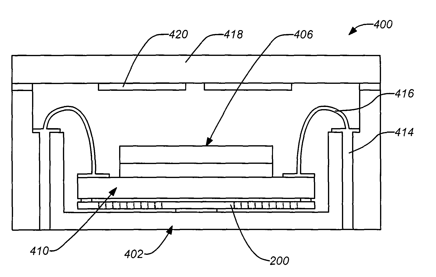
The patent describes an isolator that can be used to protect a microelectromechanical system (MEMS) die from external stresses and temperature changes. The isolator consists of a single layer with small bond pads attached to the MEMS die and a vacuum package bonded to the single layer. The isolator has a central region and a plurality of radial isolation beams that provide thermal and mechanical isolation. The isolator can be easily inserted into existing packaging and can tolerate large displacements with minimal stress. The method for producing the isolator involves etching a single layer, bonding a vacuum package to the central region, and bonding the MEMS die to the isolated pads at the periphery of the single layer. The isolator can be used in a disc resonator gyroscope to measure motion and can be modified accordingly.

Problems solved by technology

Thus, excessive stress or distortion to the package, from either CTE mismatch or external stress, may be absorbed by the isolator and will not be transmitted to the MEMS die.

Method used


Image

  • Method of producing an isolator for a microelectromechanical system (MEMS) die
  • Method of producing an isolator for a microelectromechanical system (MEMS) die
  • Method of producing an isolator for a microelectromechanical system (MEMS) die

Examples


Embodiment Construction

[0032]1. Overview

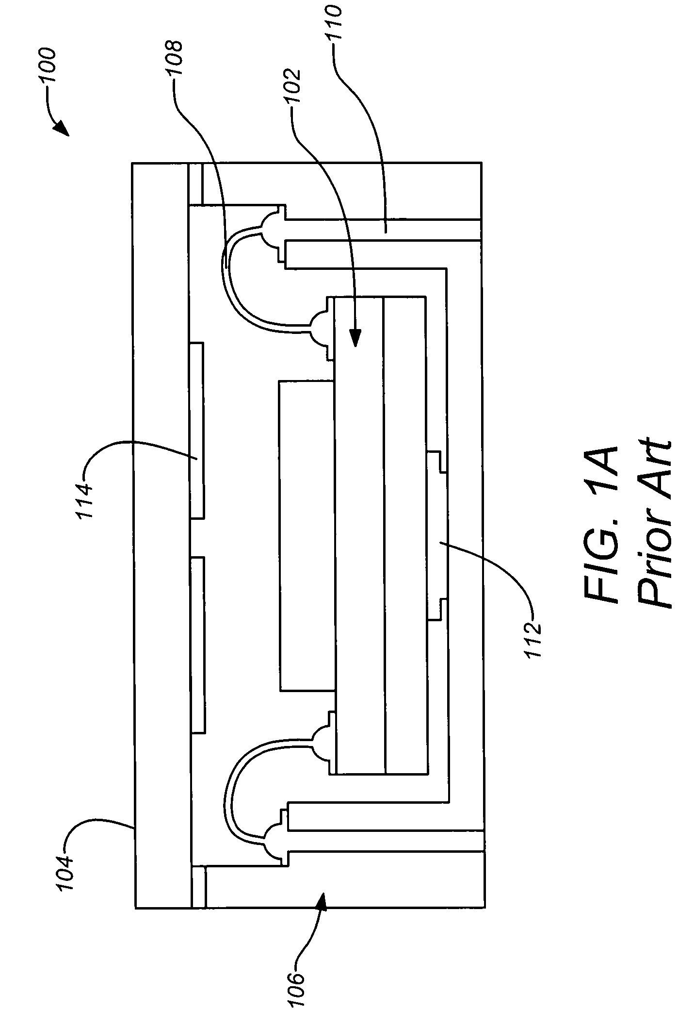
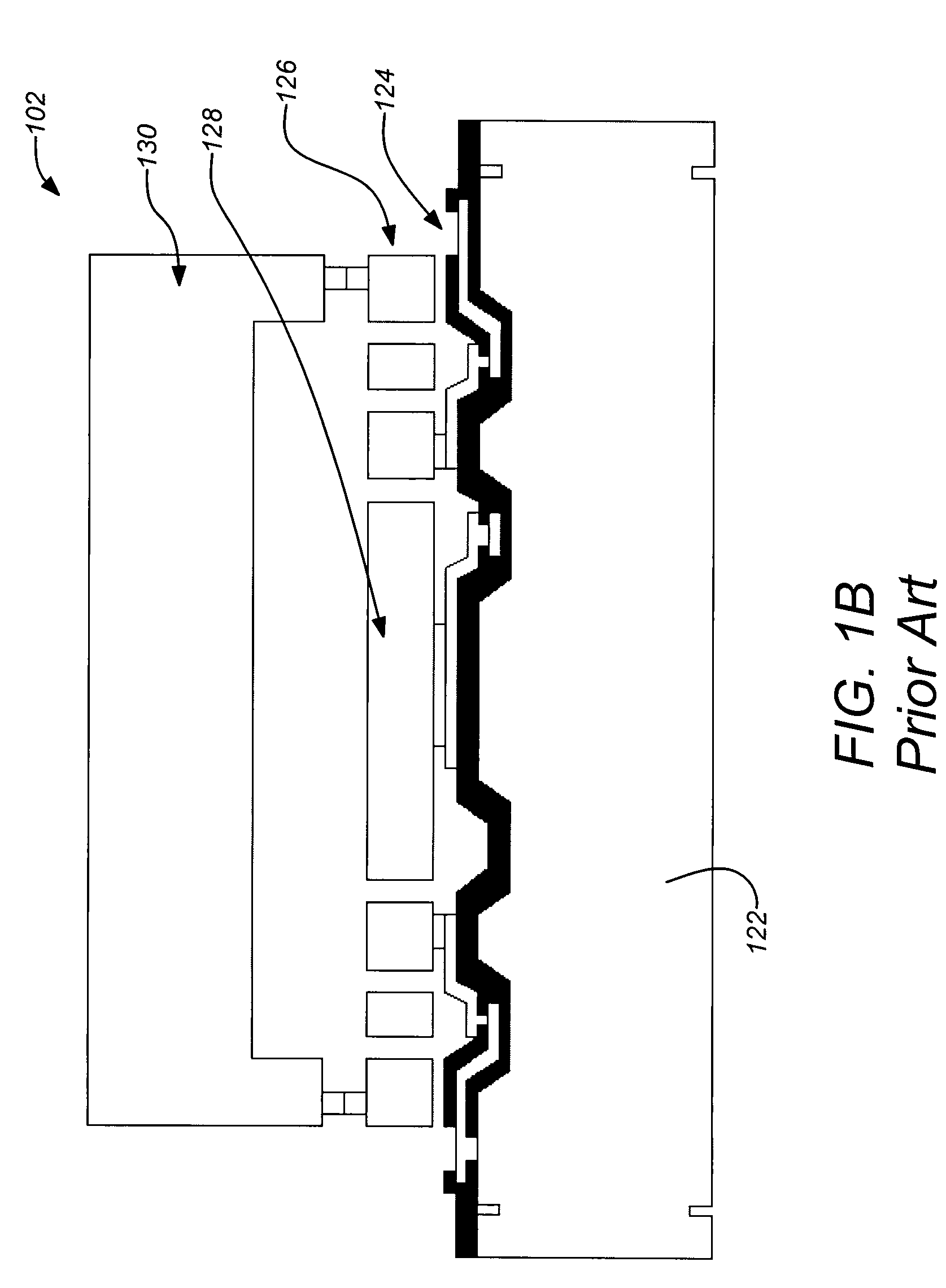
[0033]A thermal and mechanical isolator has been conceived to overcome the deficiencies described above. Embodiments of the present disclosure employ a single layer isolator that can replace the large bond pad of a conventional DRG MEMS die (e.g. as described in FIGS. 1A & 1B in the next section). The isolator may be inserted between the MEMS die and the leadless chip carrier (LCC) package bottom in a known DRG design. As used herein, a MEMS die may be any die that includes MEMS device. For example, a MEMS die may comprise a MEMS device manufacture from a semiconductor material (e.g. silicon) or an insulator (e.g. quartz). The structure of the isolator comprises a single semiconductor layer having a central region and a plurality of substantially radial isolation beams extending therefrom, each to a bond pad arranged in a radial symmetric pattern. The bond pads are bonded to the MEMS die, e.g. a DRG die, and the vacuum package is bonded to the central region of the ...


PUM

PropertyMeasurementUnit
temperatureaaaaaaaaaa
diameteraaaaaaaaaa
diameteraaaaaaaaaa

Abstract

A single layer micromachined thermal and mechanical isolator may be bonded between a microelectromechanical system (MEMS) die and package. Small bond pads of the isolator are attached to the periphery of the die. The isolator material may be chosen to match that of the die, reducing CTE mismatch. Long thin isolation beams can be used to provide thermal isolation against external temperature changes, which may be conducted through the package. Weak and flexible beams can be used to tolerate large displacements with very little resistance. Thus, excessive stress or distortion to the package, from either CTE mismatch or external stress, may be absorbed by the isolator and will not be transmitted to the MEMS die. Beam rigidity may be designed to attenuate vibration of particular frequency range. The isolator can be readily inserted into an existing disc resonator gyroscope package in one thermal compression bond step.

Description

CROSS-REFERENCE TO RELATED APPLICATIONS[0001]This application is related to the following co-pending applications, which are all incorporated by reference herein:[0002]U.S. patent application Ser. No. 11 / 458,911, filed Jul. 20, 2006, and entitled “DISC RESONATOR GYROSCOPES”, by Kubena et al.;[0003]U.S. patent application Ser. No. 11 / 757,395 (Application Publication No. 2008-0295622A1), filed Jun. 4, 2007, and entitled “PLANAR RESONATOR GYROSCOPE WITH CENTRAL DIE ATTACHMENT”, by Challoner;[0004]U.S. patent application Ser. No. 11 / 615,872, filed Dec. 22, 2006, and entitled “VIBRATORY GYROSCOPE WITH PARASITIC MODE DAMPING”, by Whelan et al.; and[0005]U.S. patent application Ser. No. 11 / 831,822, filed Jul. 31, 2007, and entitled “DISC RESONATOR INTEGRAL INERTIAL MEASUREMENT UNIT”, by Challoner et al.BACKGROUND OF THE INVENTION[0006]1. Field of the Disclosure[0007]The present disclosure relates to gyroscopes, and in particular to manufacturing disc resonator gyroscopes. More particularly...

Claims


Application Information

Patent Timeline
Patent Type & Authority Patents(United States)
IPC IPC(8): H05K3/00
CPCB81B7/0058G01C19/5684G01C25/00B81B2201/0242Y10T29/49128Y10T29/49117Y10T29/49155Y10T29/49124
Inventor GE, HOWARD H.CHALLONER, A. DORIAN
Owner THE BOEING CO
Learn More