
Device and method for producing a uniform temperature distribution in an object during a precipitation process

a technology of precipitation process and temperature distribution, which is applied in the direction of electrolysis components, emergency power supply arrangements, electric devices, etc., can solve the problems of destroying the rod, relatively high inductive losses, and the device proposed in the publication is complex, so as to reduce or eliminate interference

Inactive Publication Date: 2012-12-11
AEG POWER SOLUTIONS BV
View PDF4 Cites 0 Cited by
  • Summary
  • Abstract
  • Description
  • Claims
  • Application Information

AI Technical Summary

Benefits of technology

[0013]The object is attained by the invention in that the device has at least one frequency converter which is suitable and configured to supply electric current from the power grid to the at least one silicon rod connected to the at least one output. The electric current provided by the frequency converter has a higher frequency than the current provided by the AC current regulator. The higher frequency current is urged by the skin affect toward the outer regions of the silicon rod, whereas the lower frequency current causes a high current density in the core. By superimposing the higher frequency current and the low frequency current, an overall more homogeneous current density is attained, which results in a more uniform temperature distribution across the cross-section of the silicon rod.
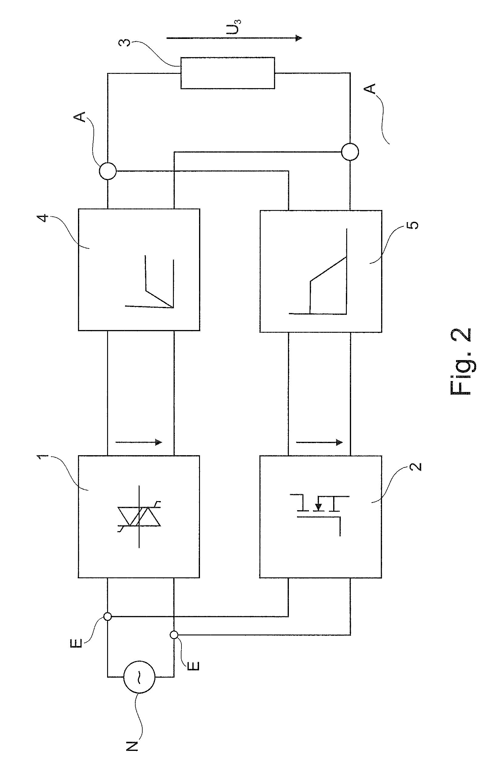
[0021]Conversely, the frequency converter can be decoupled from the AC current regulator by connecting capacitors in the series with the frequency converters, which in conjunction with the silicon rods connected to the outputs of the device form high-pass filters, thereby reducing or eliminating interference from the AC current regulator on the frequency converters.

Problems solved by technology

The silicon can then flow out of the rod, destroying the rod.
The device proposed in the publication is complex, because a second heater, namely the eddy current heater, must be provided in addition to the conventional resistance heater for heating the silicon rods.
The method disclosed in the document DE 198 82 833 T1, namely to supply the silicon rods either only with low-frequency currents or only with high or medium frequency currents, disadvantageously generates relatively high inductive losses when only a high or medium frequency voltage is supplied to the silicon rod.

Method used


Image

  • Device and method for producing a uniform temperature distribution in an object during a precipitation process
  • Device and method for producing a uniform temperature distribution in an object during a precipitation process
  • Device and method for producing a uniform temperature distribution in an object during a precipitation process

Examples


Embodiment Construction

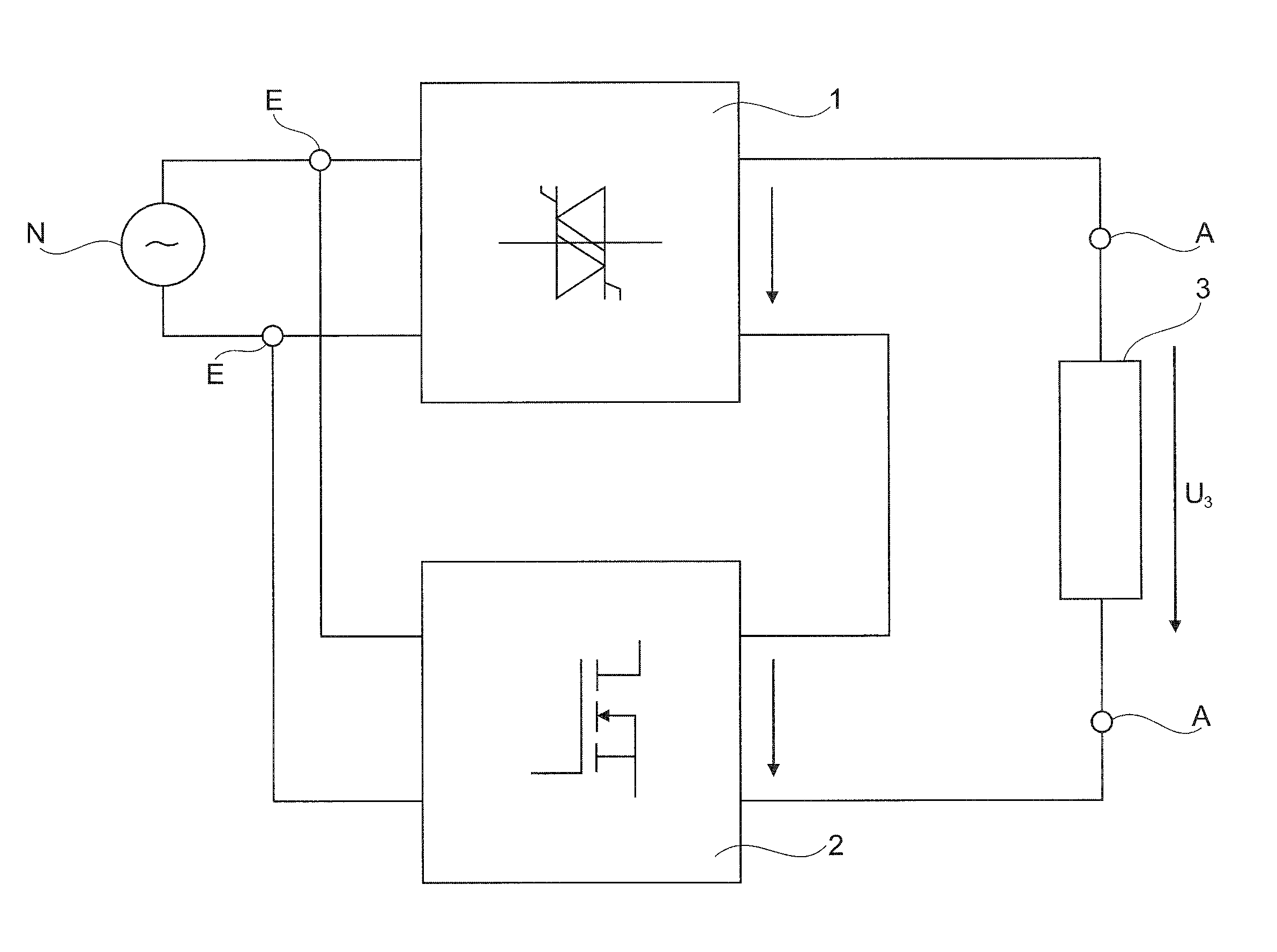
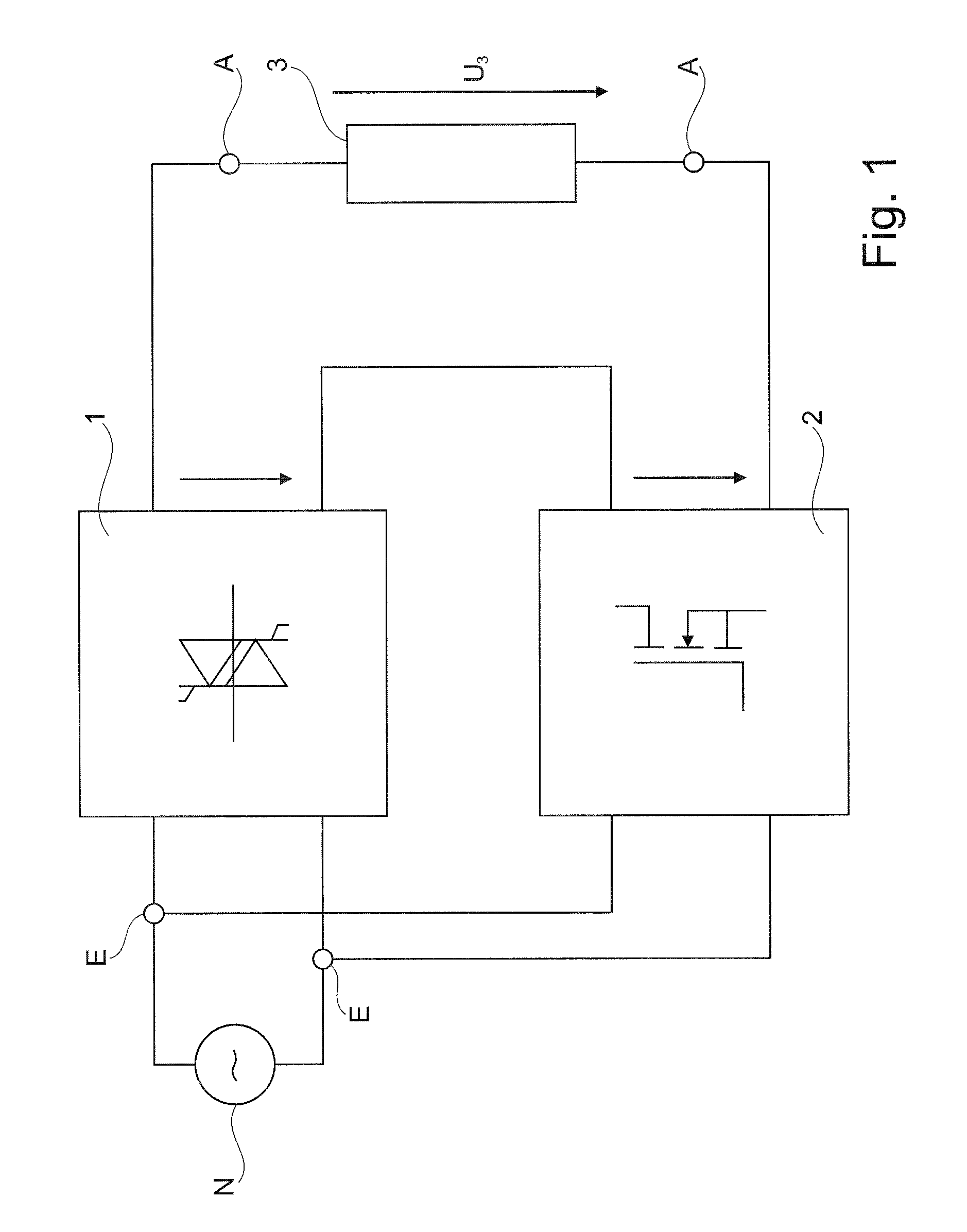
[0034]FIGS. 1, 2 and 3 illustrate simplified block circuit diagrams of devices according to the invention. Only the power paths of the devices of the invention are illustrated in FIGS. 1, 2 and 3. Lines for control or regulating signals and sensor signals are not shown in FIGS. 1, 2 and 3. The same types of elements illustrated in the device of FIG. 1, the device of FIG. 2, and the device of FIG. 3 have identical reference symbols.

[0035]The device of the invention illustrated in FIG. 1 for supplying current to a silicon rod during precipitation of silicon according to the Siemens process has an input E with two terminals E1, E2. The input E of the device is connected to the power grid N supplying electric energy. A corresponding AC current regulator 1 and a frequency converter 2 are each connected to the input E. Both the AC current regulator 1 and the frequency converter 2 can receive electric energy from the power grid N via the input E.

[0036]Both the AC current regulator 1 and th...


PUM

PropertyMeasurementUnit
surface temperatureaaaaaaaaaa
temperatureaaaaaaaaaa

Abstract

The present invention relates to a device for supplying current to at least one silicon rod (3) during precipitation of silicon with the Siemens process, wherein the device has at least one input (E) suitable and configured for connecting the device to an electric power grid (N) for supplying electric energy, at least one output (A) to which the at least one silicon rod (3) can be connected, at least one AC current regulator (1) which is suitable and configured to supply the at least one silicon rod (3) connected to the at least one output (A) with electric current from the electric power grid (N), wherein the device further includes at least one frequency converter (2) which is suitable and configured to supply the at least one silicon rod (3) connected to the at least one output (A) with electric current from the electric power grid (N), wherein the electric current has a higher frequency than the current provided by the AC current regulator (1).

Description

BACKGROUND OF THE INVENTION[0001](1) Field of the Invention[0002]The present invention relates to a device for supplying current to at least one silicon rod during precipitation of silicon according to the Siemens process. The invention further relates to a method for supplying current to at least one silicon rod during precipitation of silicon according to the Siemens process using the device.[0003](2) Description of Related Art[0004]Devices for supplying current to a silicon rod during precipitation of silicon according to the Siemens process are known in the art. Such devices have an input for connecting the device to an electric power grid for supplying electric energy. The devices further have at least one output for connection to one or several silicon rods. One or several AC current regulators supply electric current from the electric power grid to the silicon rod(s) connected to the output(s). The current intensity and the voltage and hence also the electric power thermally ...

Claims


Application Information

Patent Timeline
Patent Type & Authority Patents(United States)
IPC IPC(8): H02J7/00
CPCG05D23/1917C01B33/035C23C16/46C23C16/24H01L21/0262
Inventor WALLMEIER, PETER
Owner AEG POWER SOLUTIONS BV
Learn More