
Method and system for artifact reduction

a technology of artifacts and methods, applied in the field of artifact reduction methods and systems, can solve the problems of large artifact signals, inability to adapt to the dynamic nature of stimulation artifacts, and inability to move to m-size electrodes,

Active Publication Date: 2012-12-18
INTERUNIVERSITAIR MICRO ELECTRONICS CENT (IMEC VZW)
View PDF2 Cites 36 Cited by
  • Summary
  • Abstract
  • Description
  • Claims
  • Application Information

AI Technical Summary

Benefits of technology

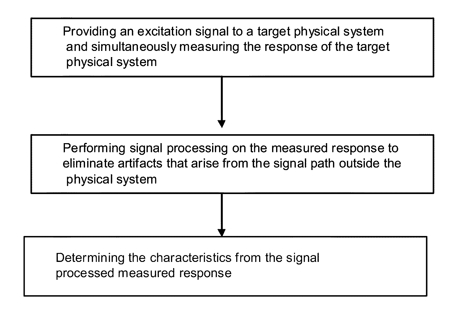
[0012]The present disclosure provides a method for obtaining characteristics of a target physical entity. The method includes providing an excitation signal to the target physical entity and simultaneously measuring the response of the target physical entity; performing analog signal processing on the measured response to eliminate artifacts that arise from a signal path outside the target physical entity (system) and determining the characteristics from the signal processed measured response whereby the excitation signal and the analog signal processing are selected such that after analog signal processing of the measured signal, the analog measured signal contains artifacts which are localized in time.
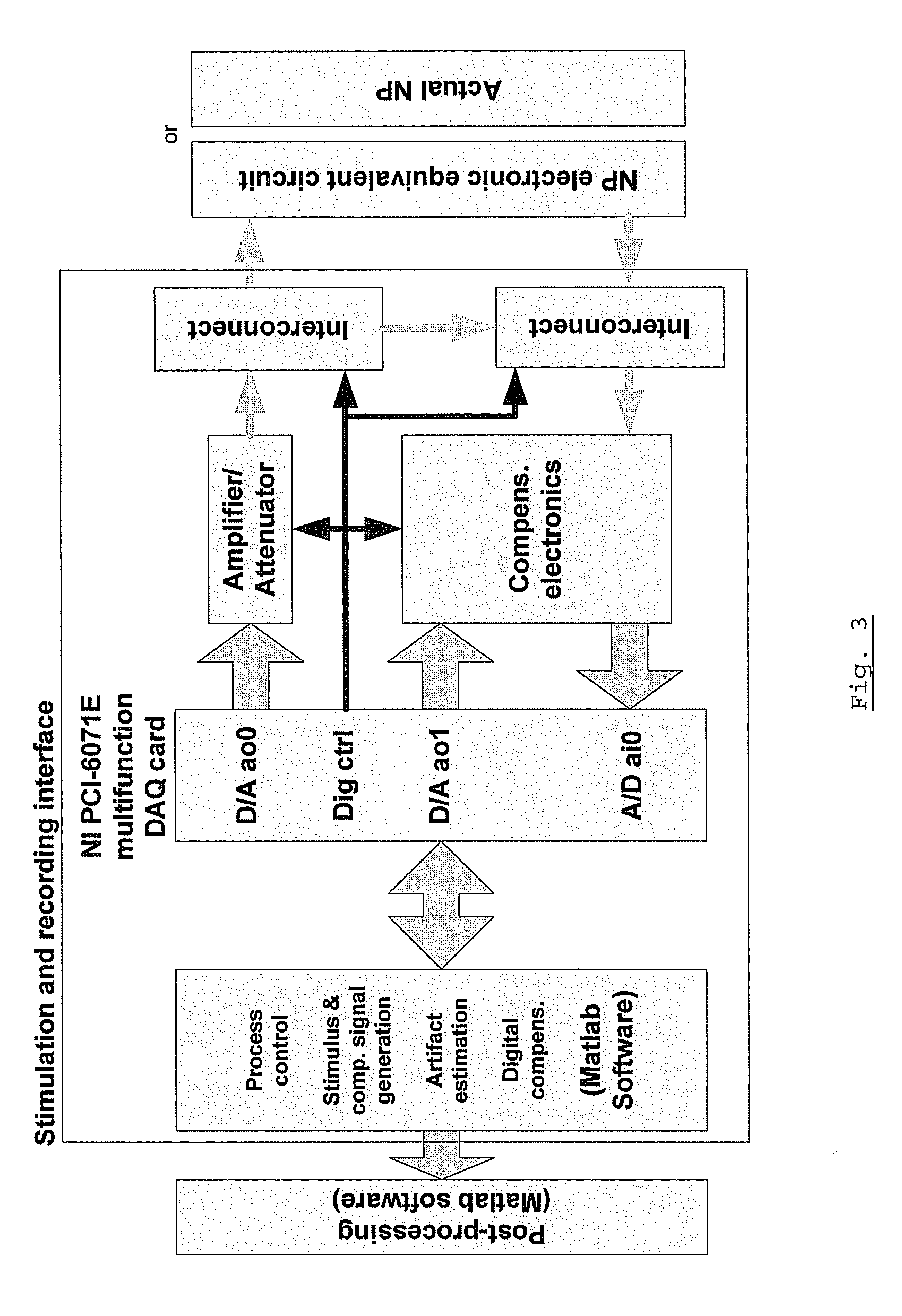
[0020]In an embodiment, a system or architecture is presented for implementing the method. The system includes an excitation source for providing an excitation signal to the target physical entity and a sensor for simultaneously measuring the response of the target physical entity; signal processing element for performing signal processing on the measured response to eliminate artifacts that arise from a signal path outside the target physical entity and a computing element for determining the characteristics from the signal processed measured response. The system allows the selection of a predetermined excitation pulse and the signal processing element is selected such that after analog signal processing of the measured signal, the analog measured signal contains artifacts which are localized in time. Preferably, the excitation source and sensor of the system are located on a μm-sized probe able to discriminate individual action potential originating from a limited number of electrogenic cells.

Problems solved by technology

However, most techniques suffer from an inability to adapt to the dynamic nature of stimulation artifact, due to the non-linearities of the stimulation procedure and hence suffer residual artifact.
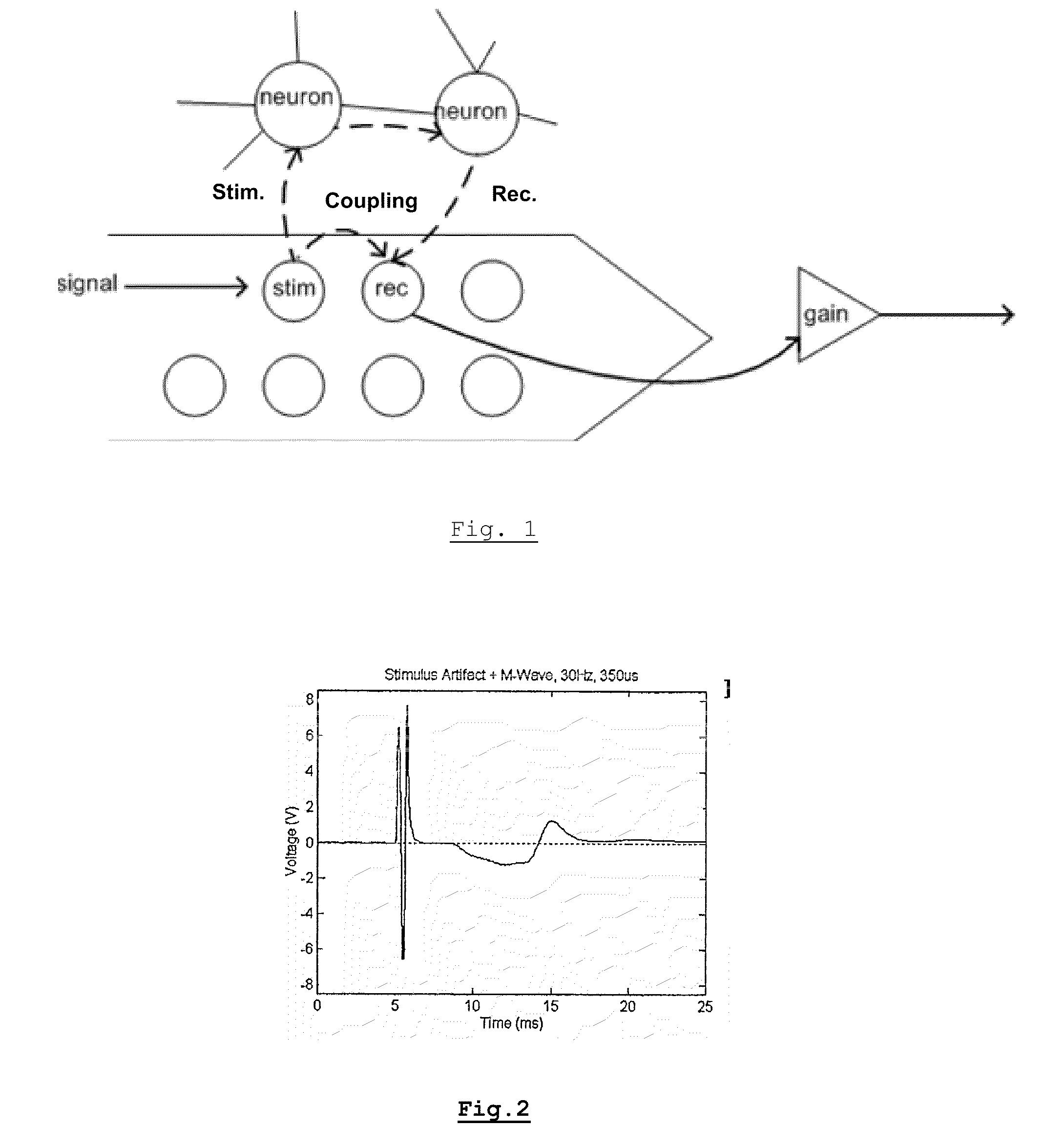
In such small neural probes, simultaneous stimulation and recording lead to large artifact signals due to direct coupling path between the closely spaced electrodes.
Moving to μm-size electrodes worsens the situation.
High-gain analog electronics is required to amplify the weak signals but gets saturated by the high stimulation artifacts.
Saturation and recovery from it can result in the loss of recording information over a multiple of the stimulus duration time.

Method used


Image

  • Method and system for artifact reduction
  • Method and system for artifact reduction
  • Method and system for artifact reduction

Examples


Embodiment Construction

[0054]In the following detailed description, reference is made to the accompanying drawings, which form a part hereof. In the drawings, similar symbols typically identify similar components, unless context dictates otherwise. The illustrative embodiments described in the detailed description, drawings, and claims are not meant to be limiting. Other embodiments may be utilized, and other changes may be made, without departing from the spirit or scope of the subject matter presented herein. It will be readily understood that the aspects of the present disclosure, as generally described herein, and illustrated in the Figures, can be arranged, substituted, combined, separated, and designed in a wide variety of different configurations, all of which are explicitly contemplated herein.

[0055]For the purpose of this disclosure, the term “excitation” used in the present document has the same meaning compared to the term “stimulation” and both can thus be used interchangeably. The terms “meas...


PUM

PropertyMeasurementUnit
voltage gainaaaaaaaaaa
residual artifactaaaaaaaaaa
voltageaaaaaaaaaa

Abstract

A method is presented for obtaining characteristics of a target physical entity by providing an excitation signal to the target physical entity and simultaneously measuring the response of the target physical entity. Analog signal processing is performed on the measured response to eliminate artifacts arising from a signal path outside the target physical entity and determining the characteristics from the signal processed measured response. The excitation signal and the analog signal processing are selected such that after analog signal processing of the measured signal, the analog measured signal contains artifacts which are localized in time.

Description

CROSS-REFERENCE TO RELATED APPLICATIONS[0001]This application claims priority to U.S. Provisional Application Ser. No. 61 / 098,166 filed Sep. 18, 2008, the contents of which are incorporated by reference herein in its entirety.BACKGROUND[0002]Since EMG, ENG and EEG signals are all fundamentally electrophysiological signals, a technique developed to remove stimulus artifact contamination present in any of the biopotential recording, may be modified and used to remove artifact from the other types. These techniques may reduce the effect of stimulus artifact and improve the fidelity of the recorded signals. These stimulus artifacts are due to direct coupling path between the closely spaced electrodes. However, most techniques suffer from an inability to adapt to the dynamic nature of stimulation artifact, due to the non-linearities of the stimulation procedure and hence suffer residual artifact.[0003]Both analog and digital (software-based) techniques have been developed to reduce these...

Claims


Application Information

Patent Timeline
Patent Type & Authority Patents(United States)
IPC IPC(8): G06F15/00C12M1/34
CPCA61B5/04017A61B5/7217A61B5/0476A61B5/316A61B5/369G01N33/4836
Inventor EBERLE, WOLFGANG
Owner INTERUNIVERSITAIR MICRO ELECTRONICS CENT (IMEC VZW)
Learn More