Expandable trans-septal sheath

a transseptal and expandable technology, applied in the field of medical devices, can solve the problems of high cost, increased time to the conduct of the procedure, and atrial septal punctures,

Active Publication Date: 2012-12-25
ONSET MEDICAL CORP
View PDF115 Cites 41 Cited by
  • Summary
  • Abstract
  • Description
  • Claims
  • Application Information

AI Technical Summary

Benefits of technology

[0013]A transluminal, radially expanding access sheath is provided according to an embodiment of the present invention. In an embodiment, the radially expanding access sheath is used to provide access to the left atrium by way of a trans-septal puncture and advancement in the atrial septum dividing the right and left atriums. In an embodiment, the sheath can have an introduction outside diameter that ranges from 3 to 12 French with a preferred range of 5 to 10 French. The diameter of the sheath can be expandable to permit instruments ranging up to 30 French to pass therethrough, with a preferred range of between 3 and 20 French. The sheath can have a working length ranging between 40-cm and 200-cm with a preferred length of 75-cm to 150-cm. The ability to pass the traditional electrophysiology therapeutic and diagnostic catheters and instruments as well as larger, more innovative, instruments through a catheter introduced with a small outside diameter is derived from the ability to atraumatically expand the distal end of the catheter or sheath to create a larger through lumen to access the cardiac chambers. The ability to pass multiple catheters through a single sheath with a single septal penetration is inherently safer and less time-consuming than a multiple septal puncture procedure. The expandable distal end of the catheter can comprise between 5% and 95% of the overall working length of the catheter. The proximal end of the catheter is generally larger than the distal end to provide for pushability, torqueaqbility (preferably approximately 1:1 torqueability), steerability, control, and the ability to easily pass large diameter instruments therethrough. In an embodiment, the sheath can be routed to its destination over one or more already placed guidewires with a diameter ranging from 0.010 inches up to 0.040 inches and generally approximating 0.035 to 0.038 inches in diameter. An advantage of approaching the treatment site by the veins, instead of the arteries, is that the venous pressure is lower than that in the arterial system, thus reducing the potential for catastrophic hemorrhage during the procedure. Another advantage of the system is that the sheath and dilator assembly are flexible enough to track over a guidewire and be steered by either the guidewire or by a Brockenbrough needle, inserted through the central lumen of the dilator.

Problems solved by technology

However, problems sometime arise, when trying to pass the guide catheter across the atrial septum, in that the tract generated by the Brockenbrough needle and Mullins catheter closes too tightly to allow passage of the guide catheter.
A risk of atrial septal punctures includes potentially perforating the aorta, a high-pressure outlet line, which resides quite close to the atrial septum.
One of the primary issues that arise during electrophysiology procedures in the heart is the need to remove and replace multiple instruments multiple times, which is highly expensive and adds substantial time to the conduct of the procedure.

Method used


Image

  • Expandable trans-septal sheath
  • Expandable trans-septal sheath
  • Expandable trans-septal sheath

Examples


Embodiment Construction

[0060]The invention may be embodied in other specific forms without departing from its spirit or essential characteristics. The described embodiments are to be considered in all respects only as illustrative and not restrictive. The scope of the invention is therefore indicated by the appended claims rather than the foregoing description. All changes that come within the meaning and range of equivalency of the claims are to be embraced within their scope.

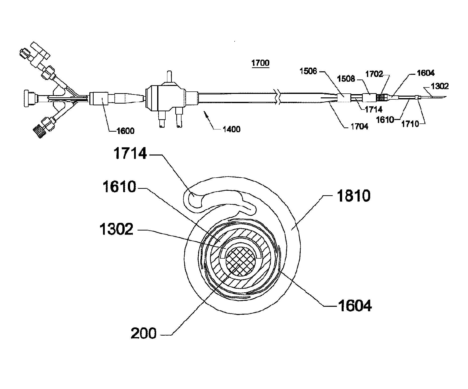
[0061]In the description below, reference will be made to a catheter or a sheath, which can be an axially elongate hollow tubular structure having a proximal end and a distal end. The axially elongate structure further can have a longitudinal axis and has an internal through lumen that extends from the proximal end to the distal end for the passage of instruments, fluids, tissue, or other materials. The axially elongate hollow tubular structure can be generally flexible and capable of bending, to a greater or lesser degree, through ...


PUM

PropertyMeasurementUnit
lengthaaaaaaaaaa
lengthaaaaaaaaaa
diameteraaaaaaaaaa

Abstract

Disclosed is an expandable transluminal sheath, for introduction into the body while in a first, low cross-sectional area configuration, and subsequent expansion of at least a part of the distal end of the sheath to a second, enlarged cross-sectional configuration. The sheath is configured for use in the vascular system and has utility in the performance of procedures in the left atrium. The access route is through the inferior vena cava to the right atrium, where a trans-septal puncture, followed by advancement of the catheter is completed. The distal end of the sheath is maintained in the first, low cross-sectional configuration during advancement to the right atrium and through the atrial septum into the left atrium. The distal end of the sheath is subsequently expanded using a radial dilatation device. In an exemplary application, the sheath is utilized to provide access for a diagnostic or therapeutic procedure such as electrophysiological mapping of the heart, radio-frequency ablation of left atrial tissue, placement of left atrial implants, mitral valve repair, or the like.

Description

CROSS-REFERENCE TO RELATED APPLICATIONS[0001]This application claims the priority benefit of U.S. Provisional Application 60 / 871,091 filed Dec. 20, 2006, the entire contents of which are hereby incorporated by reference herein.BACKGROUND OF THE INVENTION[0002]1. Field of the Invention[0003]The invention relates to medical devices for percutaneously accessing body lumens and cavities and, more particularly, to methods and devices for accessing the cardiovascular system.[0004]2. Description of the Related Art[0005]A wide variety of diagnostic or therapeutic procedures involves the introduction of a device into the vasculature through a percutaneous incision at an access site. Such regions of the vasculature, preferred for access, include both the arteries and veins, typically at peripheral locations in the body. Typical access sites include the jugular vein, the subclavian artery, the subclavian vein, the brachial artery and vein, the femoral arteries and the femoral veins. Techniques...

Claims


Application Information

Patent Timeline
Patent Type & Authority Patents(United States)
IPC IPC(8): A61M29/00
CPCA61B17/12022A61B17/12122A61B17/12159A61B17/3468A61M29/02A61B17/3423A61B18/1492A61B2017/00243A61B2017/00278A61B2017/00292A61B2017/00575A61B2017/00592A61B2017/00632A61B2017/1205A61B2017/3486A61B2018/00351A61B2018/1407A61M25/0045A61M25/0053A61M25/1011A61B17/3478
Inventor NANCE, EDWARD J.LENKER, JAYKICK, GEORGE F.NGUYEN, HYUN T.
Owner ONSET MEDICAL CORP
Why Eureka
Try Eureka