
Vacuum interface assembly

a technology of vacuum interface and assembly, which is applied in the direction of instruments, radiation measurement, measurement devices, etc., can solve problems such as errors in measurements, and achieve the effect of optimizing measurement precision

Inactive Publication Date: 2012-12-25
AMETEK INC
View PDF0 Cites 0 Cited by
  • Summary
  • Abstract
  • Description
  • Claims
  • Application Information

AI Technical Summary

Benefits of technology

[0008]This object is accomplished by a system that comprises an X-ray head module and a vacuum interface that supports the head module. The x-ray head module includes the x-ray generation and detection columns and the head control electronics, communications and cooling systems. The remote x-ray head provides flexibility to mate with a variety of vacuum equipment configurations. The head is mounted in a stainless steel containment vessel forming the interface that provides radiation shielding and incorporates one or more ports that allow x-rays to pass through the process deposition tool wall into the vacuum process tool environment or section of the vacuum process line environment. The vacuum interface is custom-fabricated to accommodate the specific mechanical requirements of a specific process tool or line. Preferably, the bottom of the vessel lies approximately 0.5″ (10 mm) from the substrate surface, and the incident x-ray beam is perpendicular to the measurement point. This height and orientation provides optimal measurement precision while ensuring that no contact occurs with the coated substrate material. X-ray ports are integrated into the base of the containment vessel. The ports allow primary beam x-rays to pass into the clean vacuum section of the deposition tool and enables X-rays fluoresced by the sample to be captured by the detector. The X-ray port is a stainless steel puck that has two apertures in it. The first aperture allows primary beam X-rays to enter the process vessel, and the second aperture allows fluoresced X-rays from the photovoltaic product to leave the process vessel. Fluoresced X-rays are counted by the X-Ray head's detector system. Beryllium windows cover the apertures in the X-ray interface port assembly. A 5 mm thickness at a 0.5 inch lateral span for each window provides sufficient axial load capacity to prevent failure at 10−9 torr. In addition, the use of Beryllium reflects infrared radiation that would otherwise strike the detector and cause erroneous measurements. The X-ray port has an o-ring seal that maintains vacuum between itself and the interface housing. The vacuum interface housing has an o-ring seal that maintains vacuum between itself and the wall of the vacuum chamber. This system (X-ray head, vacuum interface housing and X-ray vacuum interface port(s), enables XRF measurements to be performed with the X-ray head remaining in an air environment.

Problems solved by technology

In addition, the use of Beryllium reflects infrared radiation that would otherwise strike the detector and cause erroneous measurements.

Method used


Image

  • Vacuum interface assembly
  • Vacuum interface assembly
  • Vacuum interface assembly

Examples


Embodiment Construction

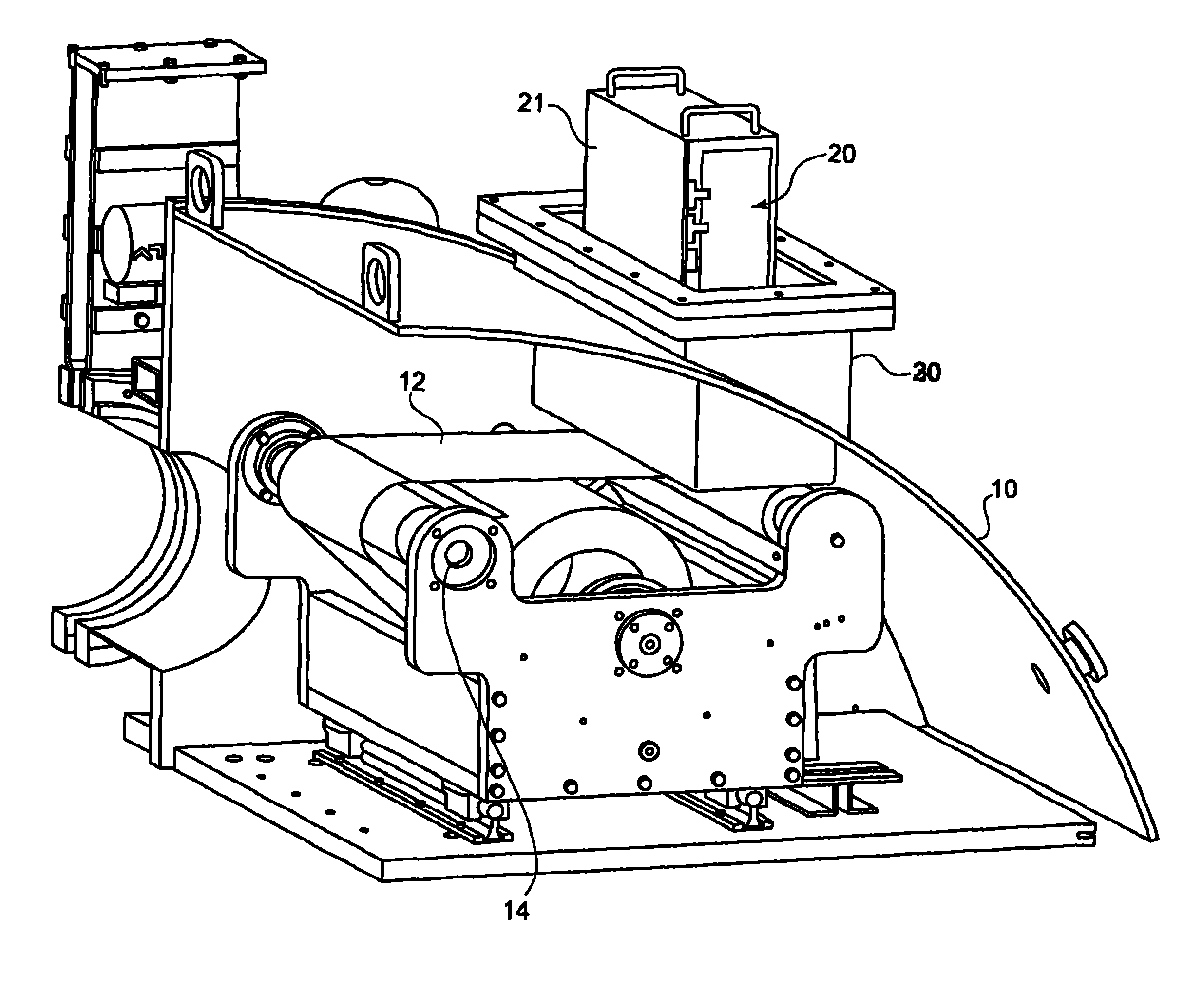
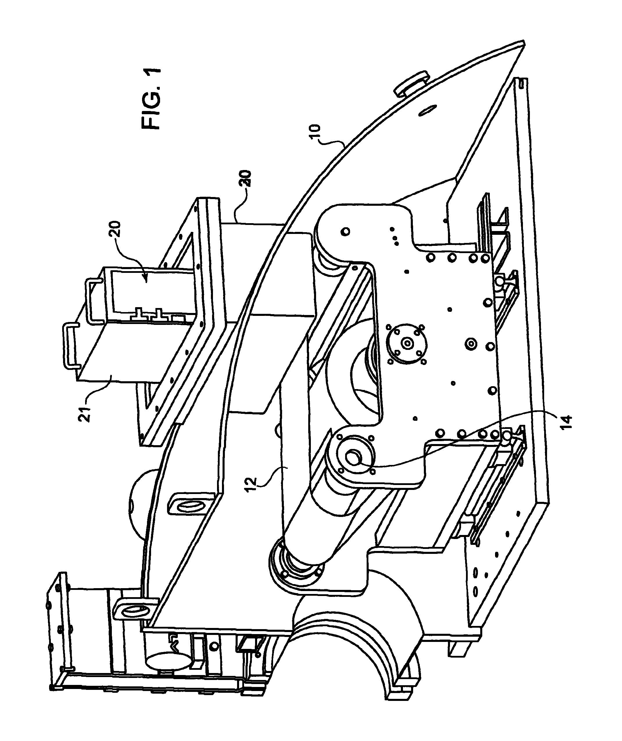
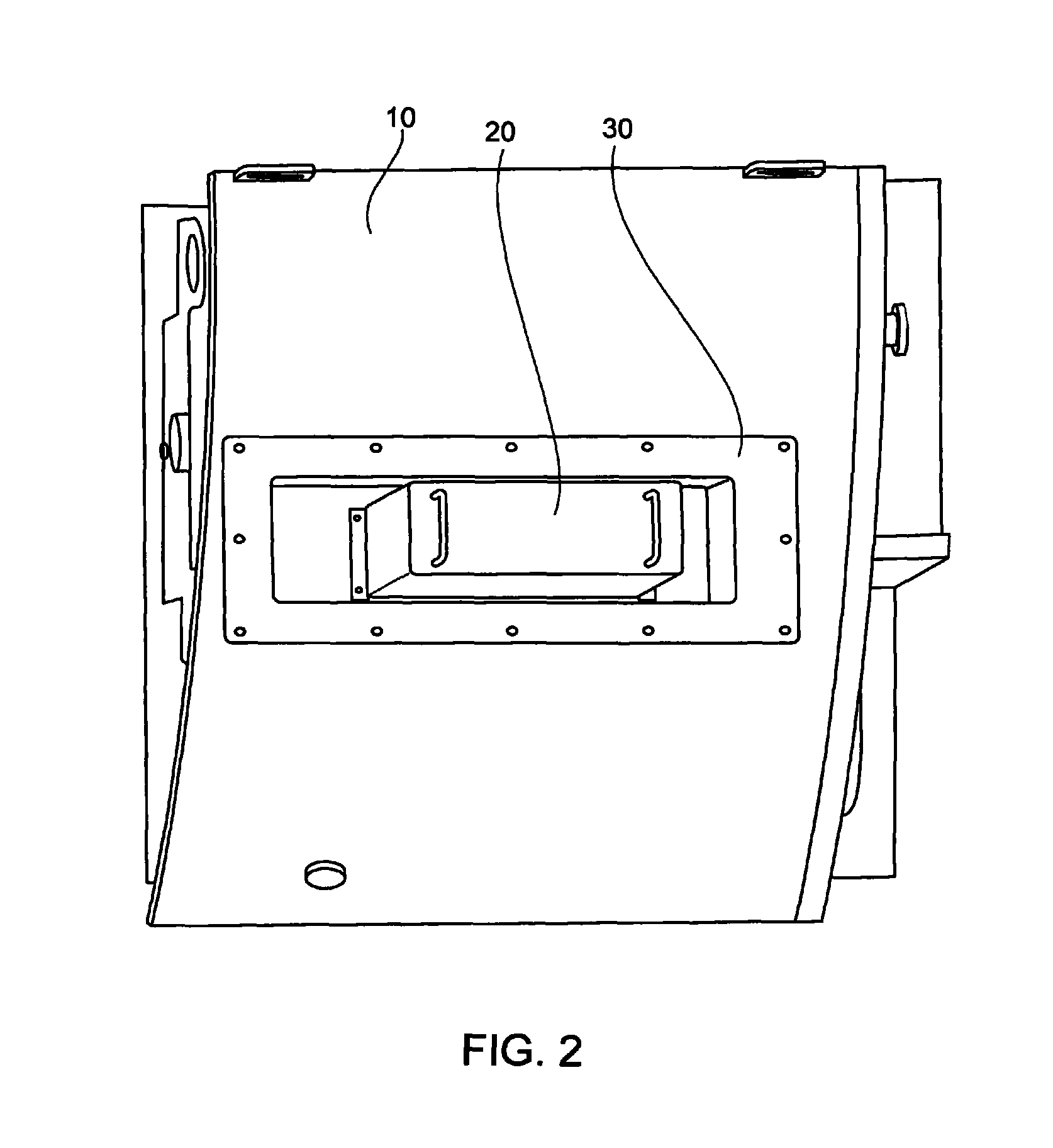
[0021]Referring now in detail to the drawings, FIGS. 1 and 2 show a vacuum deposition chamber 10 in which a substrate is unwound from a roll 14 for inspection by an X-ray metrology machine 20. Metrology machine 20 is mounted in a vacuum interface assembly 30, which is mounted through a hole in vacuum deposition chamber 10, and sealed to maintain the vacuum within chamber 10. This sealing can be done via an O-ring or by any known method.

[0022]As shown in FIGS. 3 and 4, vacuum interface assembly 30 comprises a housing 31 surrounded by an upper flange 32. The housing can be configured to fit metrology machines of different sizes and can be used for a static mounted machine or a linear machine, as described below with regard to FIGS. 9 and 10. At the bottom of housing 31 is an X-ray port 35.

[0023]X-ray port 35 is a steel cylinder through which two apertures 36, 37 extend, as shown in FIGS. 5 and 6. As shown in FIG. 6, aperture 36 extends through port 35 perpendicular to the plane of por...


PUM

PropertyMeasurementUnit
angleaaaaaaaaaa
thickaaaaaaaaaa
thickaaaaaaaaaa

Abstract

An X-ray metrology system for a vacuum deposition chamber includes a vacuum interface assembly mounted through an aperture in the exterior wall of the chamber and extending into the interior of the chamber. The interface assembly is formed from a housing having side walls and a bottom forming an interior chamber, and an X-ray port mounted in an aperture in the bottom of the housing. The X-ray port has two apertures therethrough, with each aperture being covered by a window of beryllium. An X-ray metrology machine having a generator and detector is disposed within the housing, and the apertures in the X-ray port are arranged so that X-rays generated by the generator pass through one of the apertures, and X-rays fluorescing off of a substrate in the deposition chamber travel through the other aperture to the detector.

Description

CROSS-REFERENCE TO RELATED APPLICATIONS[0001]This application claims priority under 35 USC §119(e) of U.S. Provisional Application Ser. No. 61 / 279,434, filed on Oct. 21, 2009.BACKGROUND OF THE INVENTION[0002]1. Field of the Invention[0003]This invention relates to an assembly for protecting an X-ray head from the heat generated in a vacuum XRF film metrology system. In particular the invention relates to a containment vessel that protects the X-ray head while allowing X-rays to penetrate through a port in the vessel to reach the substrate, and enter back through the port to a detector in the head assembly.[0004]2. The Prior Art[0005]X-ray based metrology tools are required to manufacture the active layer in copper indium gallium diselenide photovoltaic cells (CIGS PV cells) that convert sunlight to electricity. Vacuum-based processes that deposit CIGS films must be controlled in a vacuum environment to ensure acceptable commercial output. Venting to air for process control would des...

Claims


Application Information

Patent Timeline
Patent Type & Authority Patents(United States)
IPC IPC(8): G01N23/223
CPCG01N23/223G01N2223/076
Inventor REILLY, FRANCIS
Owner AMETEK INC
Learn More