Porous plain bearing with continuous variation of the borehole compression

a plain bearing and variation technology, applied in the direction of sliding contact bearings, mechanical equipment, rotary machine parts, etc., can solve the problems of 40° c, no lubricant depot in the form of grooves or nuts, and cannot guarantee the good functionality of standard plain porous bearings, etc., to achieve the effect of increasing friction, increasing wear, and increasing wear

a plain bearing and variation technology, applied in the direction of sliding contact bearings, mechanical equipment, rotary machine parts, etc., can solve the problems of 40° c, no lubricant depot in the form of grooves or nuts, and cannot guarantee the good functionality of standard plain porous bearings, etc., to achieve the effect of increasing friction, increasing wear, and increasing wear

US20060078242A1Active Publication Date: 2006-04-13GKN SINTER METALS GMBH & CO KG +1

Image

  • Porous plain bearing with continuous variation of the borehole compression
  • Porous plain bearing with continuous variation of the borehole compression
  • Porous plain bearing with continuous variation of the borehole compression

Examples


Embodiment Construction

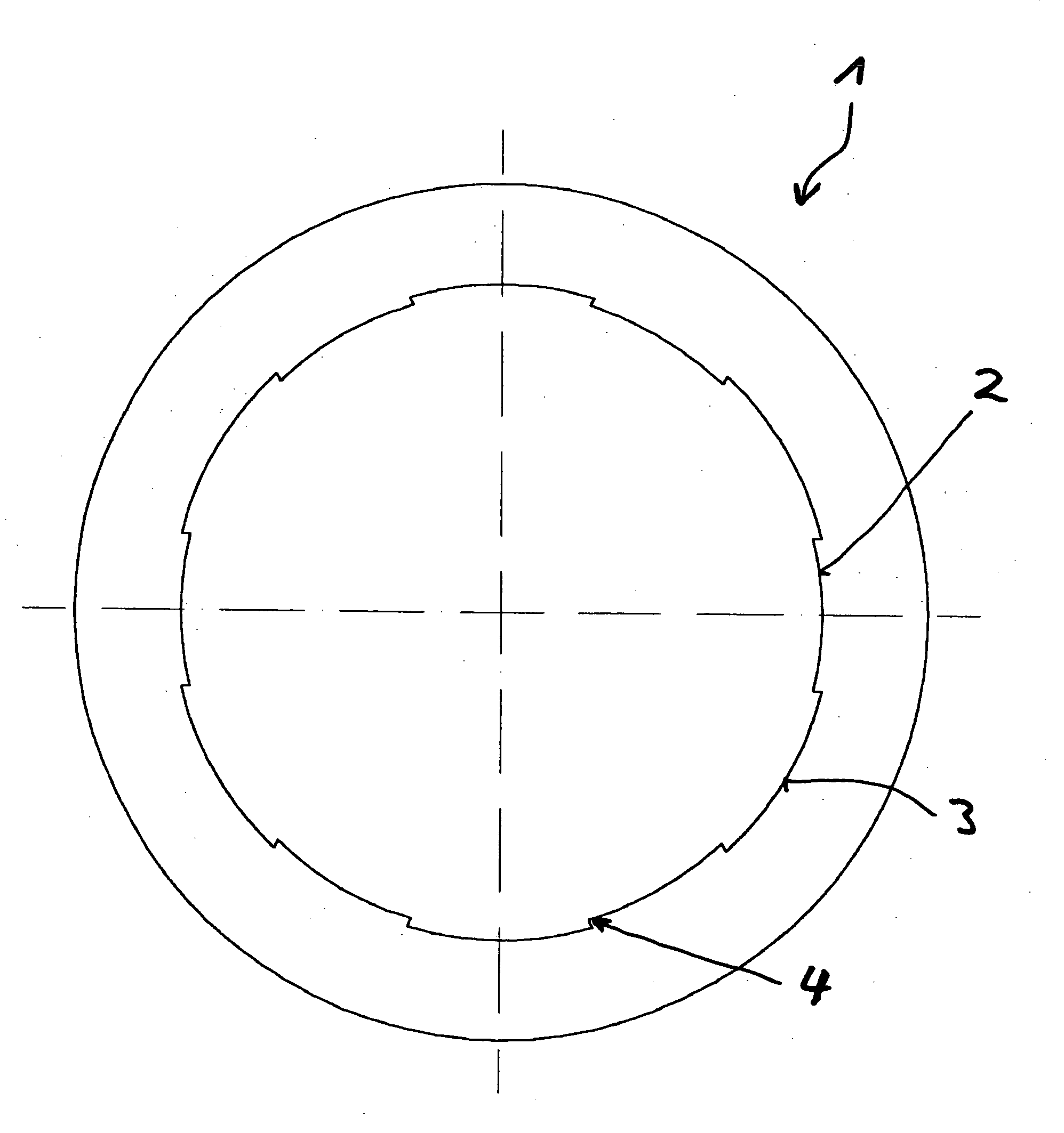
[0032]FIG. 1 illustrates plain porous bearing 1 according to the current state of the technology, e.g. of DE 199 37 567, of DE 199 47 462 and 101 07 485, whereby a crossover exists between the highly compressed areas 2 and the slightly compressed areas 3. Step 4 is sufficiently disadvantageous that during operation, the oil film on the step 4 may be stripped off such that the supply of lubricant to the bearing gap can no longer be guaranteed.

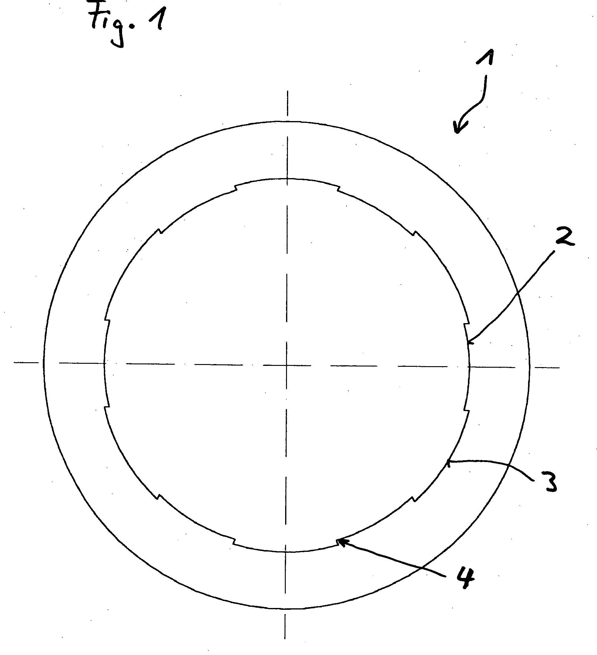
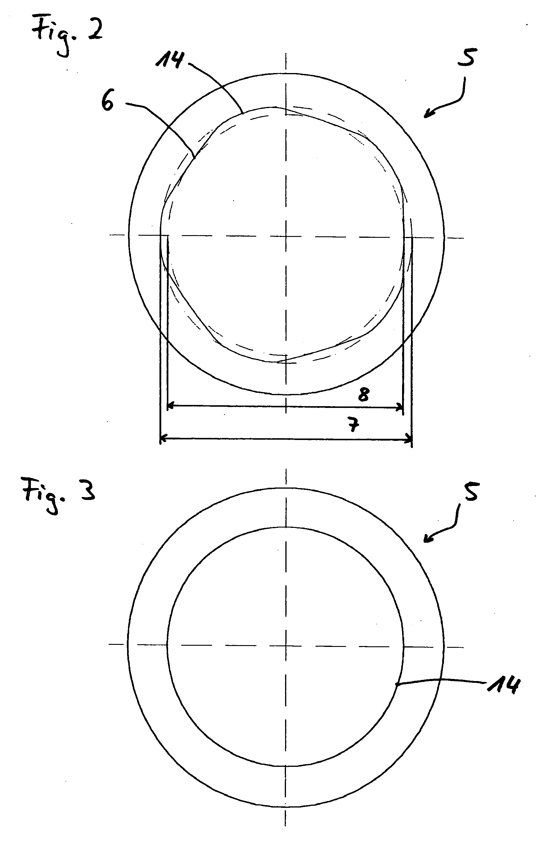
[0033]FIG. 2 illustrates bearing bore 14 of the invention-related plain porous bearing 5 after sintering. The sinusoidal profile 6 of the bearing bore is inserted into the form process and exhibits a root circle 7 (smallest bearing bore diameter) in the lowest areas, and on the highest areas a tip circle 8 (largest bearing bore diameter). The difference between the root circle 7 and the tip circle 8 of the sinusoidal pattern indicates the suppression degree of the material during calibration. The diameter of the calibration mandrel will be adju...


PUM

PropertyMeasurementUnit
diameteraaaaaaaaaa
diameteraaaaaaaaaa
bore diameteraaaaaaaaaa

Abstract

The invention pertains to a plain porous bearing for motors and transmissions with a circular bearing bore that displays, distributed alternatingly across the bearing bore, highly compressed at least approximately closed-pore areas and slightly compressed, open-pore areas, where the bearing bore diameters of the highly and slightly compressed areas are at least approximately identical. Also provided is a procedure and device for production of the bearing.

Description

CROSS-REFERENCE TO RELATED APPLICATION [0001] This is a continuation of PCT / EP2004 / 002729 filed Mar. 17, 2004, which claims priority to German Application Number 103 12 873.5 filed Mar. 22, 2003.FIELD OF THE INVENTION [0002] The invention pertains to a plain porous bearing for motors and transmissions. BACKGROUND OF THE INVENTION [0003] Plain porous bearings are utilized in many cases in motors and transmissions. Their production is cost-efficient and their application is easy. The limits of their area of application are specified by the maximum radial load. These radial loads depend on other bearing parameters such as e.g. the sinter materials, sliding speeds, lubricants, operating temperatures etc.. In contrast to plain porous bearings, substantial slide bearings can usually be applied under higher radial loads and sliding speeds, since the lubricating film that builds up between the wave and the bearing can separate the friction partners under high loads as well. In the case of p...

Claims


Application Information

Patent Timeline
13 Apr 2006
Publication
US20060078242A1
IPC
F16C33/02; F16C33/10; F16C33/14; F16C33/24
CPC
F16C33/103; F16C33/104; Y10S384/902; Y10T29/49647; F16C33/145; F16C33/24; F16C2361/61; F16C2380/26
Inventors
VOGT, ANDREAS; DORNHOFER, GERD