Physical quantity measurement device
a technology of physical quantity measurement and measurement device, which is applied in the direction of electric devices, liquid/fluent solid measurement, instruments, etc., can solve the problems of difficult to simplify the load is likely to prevent or limit the load is likely to malfunction. to prevent or limit the communication between the physical quantity measurement device, etc., to achieve the effect of simplifying the construction of the external devi
- Summary
- Abstract
- Description
- Claims
- Application Information
AI Technical Summary
Benefits of technology
Problems solved by technology
Method used
Image

Examples
1st embodiment
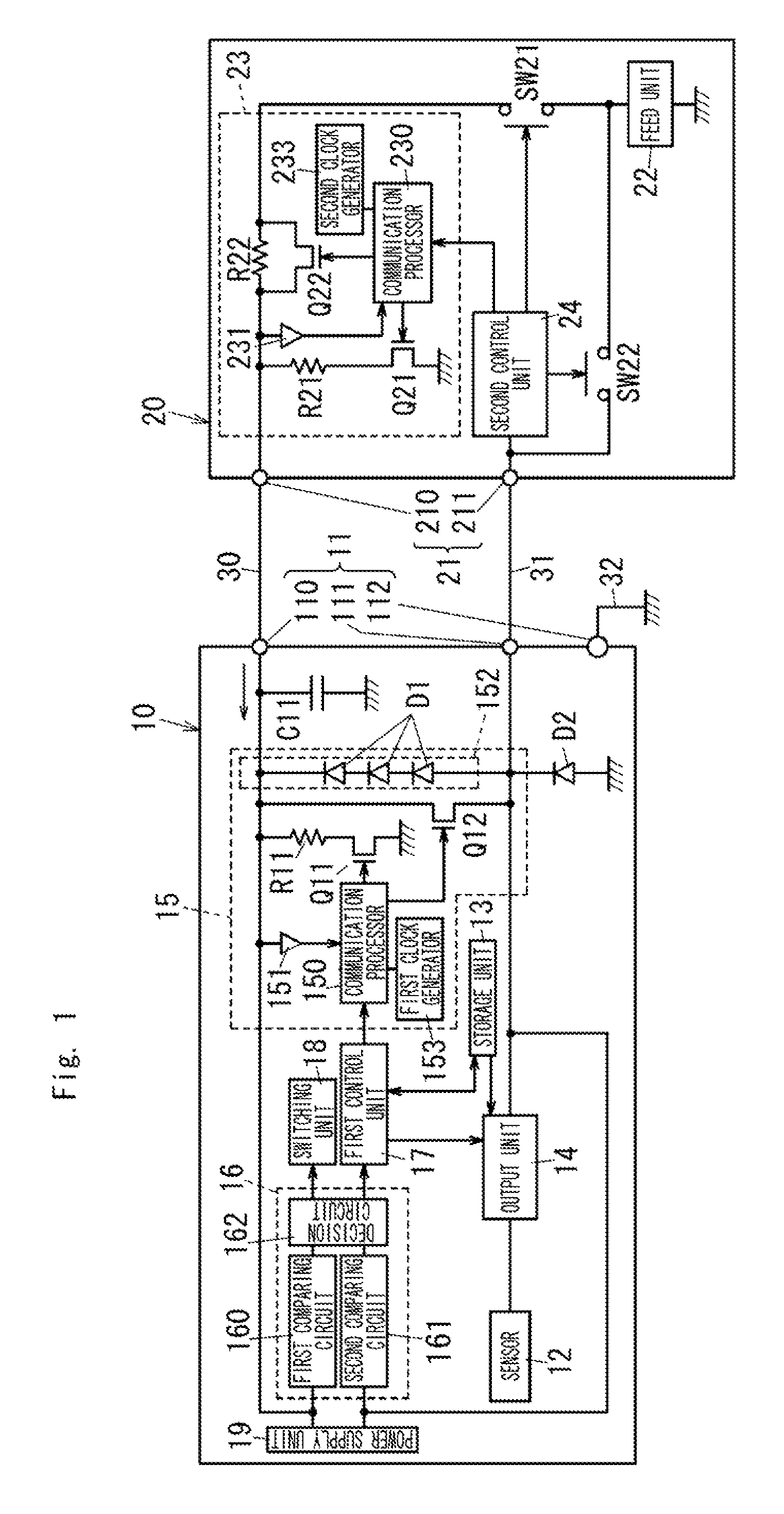
[0048]A physical quantity measurement device 10 according to the present embodiment is applied to a physical quantity detecting system shown in FIG. 1.
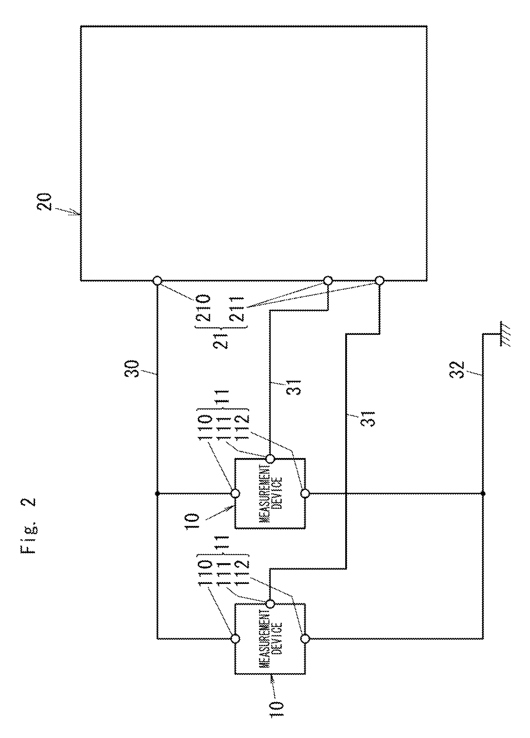
[0049]Referring FIG. 2, the physical quantity detecting system involves a plurality of physical quantity measurement devices 10, and a management device 20 as an external device. The measurement device 10 is used as a slave, and the management device 20 is used as a master. This physical quantity detecting system is applicable to engine control system employing an Electronic Control Unit.
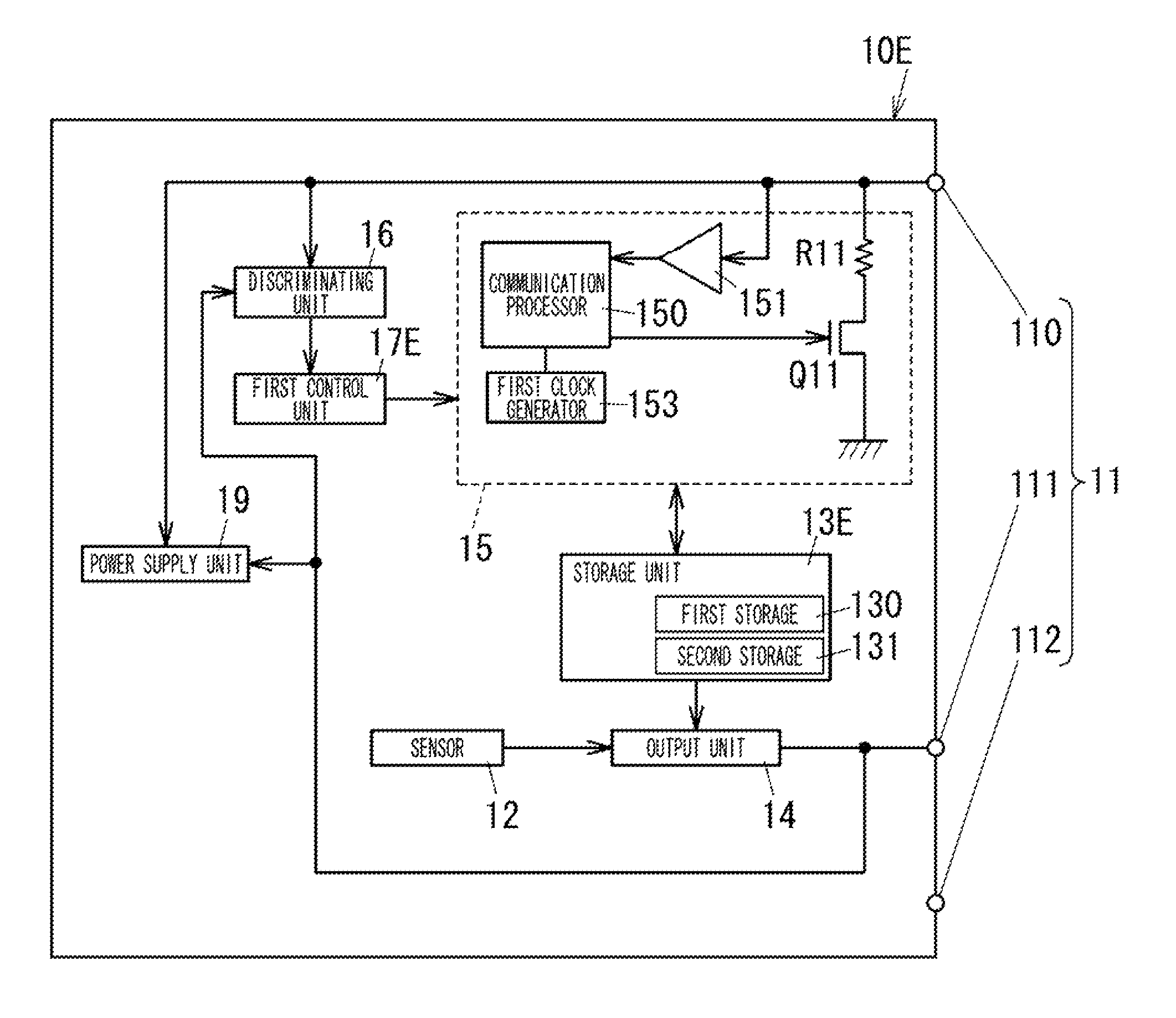
[0050]The measurement device 10 includes a terminal unit (a first terminal unit) 11, a sensor 12, a storage unit 13, an output unit 14, a communication unit (a first communication unit) 15, a discriminating unit 16, a control unit (a first control unit) 17, a switching unit 18, and a power supply unit 19. Electrical equipment which constructs the measurement device 10 is housed in a case (not shown).
[0051]The sensor 12 is configured to detect a predet...
2nd embodiment
[0146]Now referring to FIG. 7, an explanation is made to a measurement device 10 according to the second embodiment of the present invention which is basically identical to the first embodiment except for inclusion of an associated modification of the discriminating unit 16A. Like parts are designated by like reference numerals optionally with a suffix letter of “A”, and no duplication explanation is deemed necessary.
[0147]The discriminating circuit 16A includes a third comparing circuit 163 and a fourth comparing circuit 164 in addition to the first comparing circuit 160, the second comparing circuit 161, and the decision circuit 162A.
[0148]The third comparing circuit 163 is configured to compare the electric potential of the power terminal 110 to a third threshold Vth3. The fourth comparing circuit 164 is configured to compare the electric potential of the output terminal 111 to the third threshold Vth3. Each of the comparing circuits 163 and 164 is composed of a comparator.
[0149]...
3rd embodiment
[0160]An explanation is made to a measurement device 10 according to the third embodiment of the present invention which is basically identical to the first embodiment except for inclusion of an associated modification of the discriminating unit 16. Moreover, an explanation is made to a management device 20 mentioned in the third embodiment which is basically identical to the management device 20 mentioned in the first embodiment except for inclusion of an associated modification of the second control unit 24. Like parts are designated by like reference numerals, and no duplication explanation is deemed necessary.
[0161]The second control unit 24 mentioned in the present embodiment is configured to control the second communication unit 23 such that the second communication unit 23 sends an instruction signal to the measurement device 10. The instruction signal is used for instructing the measurement device 10 to switch the operational mode to the transition mode. The second control u...
PUM
 Abstract
Description
Claims
Application Information
 - R&D
- Intellectual Property
- Life Sciences
- Materials
- Tech Scout
- Unparalleled Data Quality
- Higher Quality Content
- 60% Fewer Hallucinations
Browse by: Latest US Patents, China's latest patents, Technical Efficacy Thesaurus, Application Domain, Technology Topic, Popular Technical Reports.
© 2025 PatSnap. All rights reserved.Legal|Privacy policy|Modern Slavery Act Transparency Statement|Sitemap|About US| Contact US: help@patsnap.com