Method and electron microscope for measuring the similarity of two-dimensional images

Active Publication Date: 2013-01-08
FORSCHUNGSZENTRUM JULICH GMBH
View PDF6 Cites 0 Cited by
  • Summary
  • Abstract
  • Description
  • Claims
  • Application Information

AI Technical Summary

Benefits of technology

[0067]The method according to the invention is both faster and more precise than the methods according to the state of the art, the measurement results of which are significantly distorted, in particular by interferences in the images recorded with the microscope. If the comparison unit is able to perform the method according to the invention, the aberrations of the microscope can be determined more precisely by the evaluation unit. The adjustment command generated by the evaluation unit for the controller then prompts the lens arrangement to almost completely compensate for the existing aberrations of the microscope, without overcompensating. As a result, the interpretable resolution that can be achieved with the microscope increases.
[0068]In a further advantageous embodiment of the invention, the comparison unit comprises means for a discretization of the intensity values of the pixels of at least one of the images to 16 or fewer, and particularly to two, possible values per pixel. The image comparison can then be performed considerably faster, due to the lower volume of information to be processed. For such a quick image comparison, the comparison unit may, for example, comprise means for an exclusive Or operation (XOR) between two discretized images. However, it may also comprise a digital signal processor (DSP). In addition to the exclusive Or operation, this processor may also perform further quick comparison methods. The truth table of a logic operation used as the co

Problems solved by technology

In a manner similar to lenses for visible light, electromagnetic lenses for diffracting electrons have image defects, and these image defects can degrade the resolution capacity of the microscope.
While, in the case of conventional electron microscopes, which exclusively comprise electromagnetic circular lenses, it is possible to determine a variety of aberrations using the tilted tableau method described above, the correctable aberrations are limited to defocusing, second- and third-order astigmatism, and axial coma.
In particular, while the strongly dominating spherical aberration can be determined in a microscope fitted with circular lenses, it cannot be corrected.
The latter visual method of pattern detection is not suited for practical, daily use, due to the slow speed and subjective nature of the human comparison of patterns, so that only the machine-based comparison of patterns remains as a proven means for determining defocusing and astigmatism values in order to determine microscope aberrations.
The comparison of an experimental diffractogram to simulated diffractograms according to the state of the art is highly error-prone and imprecise, since the experimentally meas

Method used


Image

  • Method and electron microscope for measuring the similarity of two-dimensional images
  • Method and electron microscope for measuring the similarity of two-dimensional images
  • Method and electron microscope for measuring the similarity of two-dimensional images

Examples


Embodiment Construction

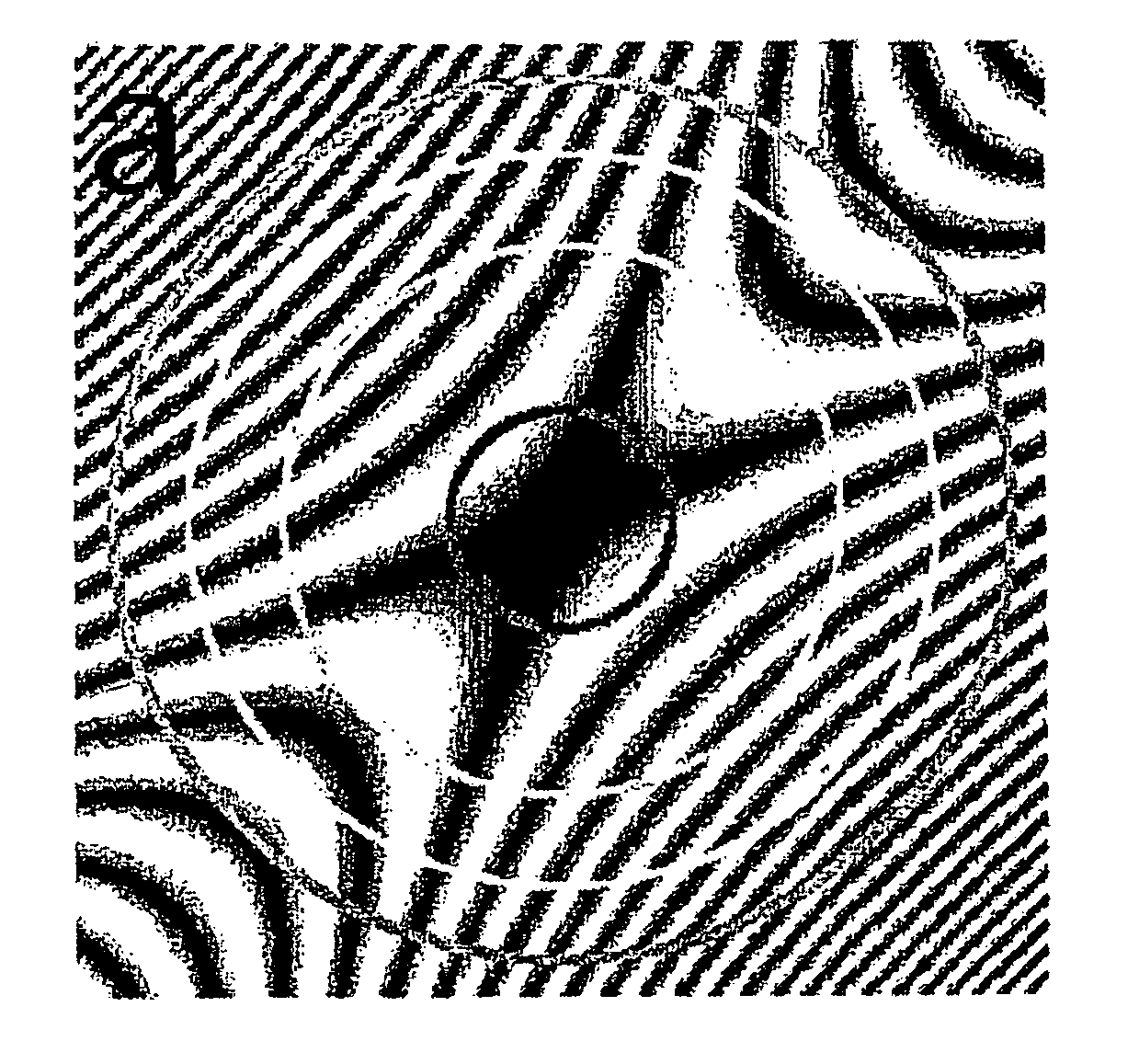
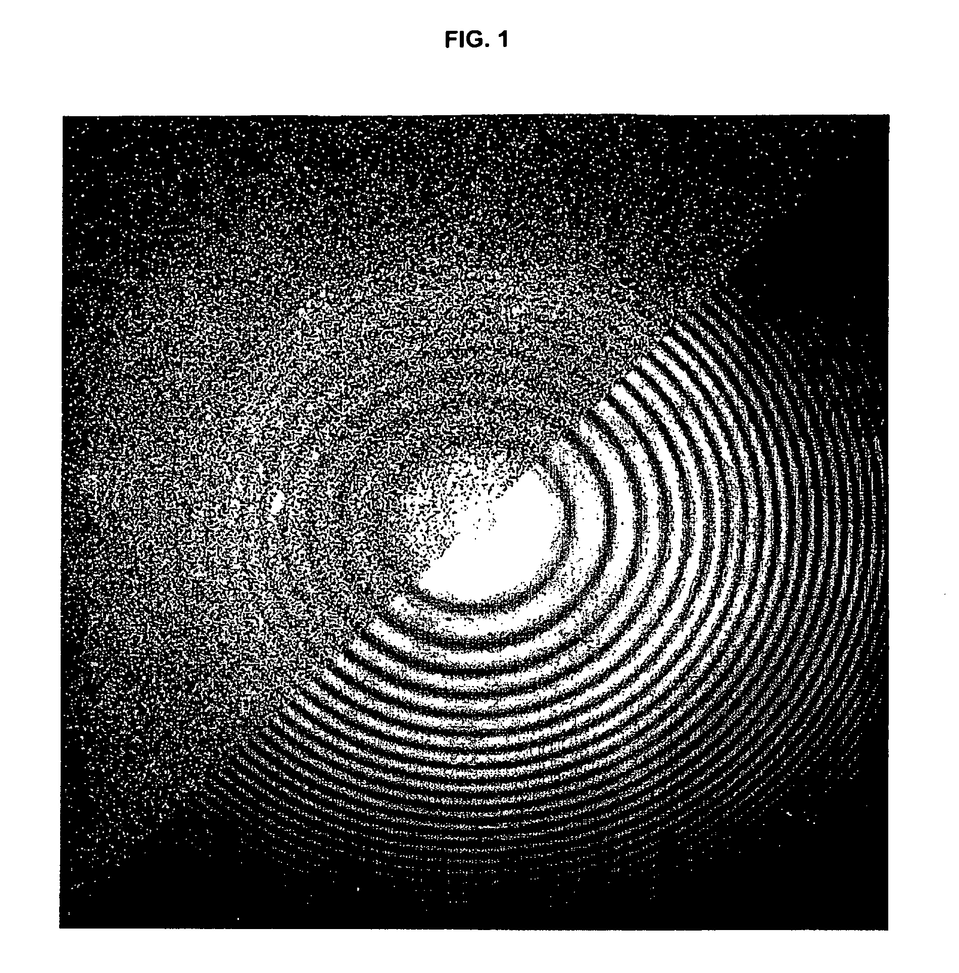
[0079]FIG. 1 shows an electron-microscopic depiction (diffractogram) of a thin amorphous object, shown in Fourier space (spatial frequency space). The upper left half shows an experimentally measured image. The lower right half shows the simulated image, which comes closest to the experimentally measured image. This simulated image embodies the useful signal present in the experimentally measured image. However, it already contains additional signals, such as damping envelopes, which inevitably occur in the experimentally measured image. In this way, this ensures that the purely visual similarity between the experimentally measured image and the simulated image is only influenced by changes of the two measurement variables of interest, which is to say defocusing and astigmatism.

[0080]The ring patterns are also referred to as Thon rings. The shape thereof depends on the angle of incidence of the electron beam, the electron wavelength, the spherical aberration constant, the effective ...


PUM


Abstract

Disclosed is a method for measuring the similarity of two-dimensional images, at least one image exhibiting an additional signal, the location dependence or symmetry properties of which are known at least approximately. The images are partitioned into mutually identical subimages such that the extension of at least one subimage in the direction of the gradient of the additional signal is smaller than the extension of this subimage in the direction perpendicular thereto. The subimages are compared separately, and the results of all comparisons are combined to form the measurement result for similarity. As a result, the method becomes insensitive to variations in the additional signal. The method is particularly suited for the determination of defocusing and astigmatism of an electron-microscopic image. For this purpose, it is important to compare the similarity of an experimentally measured image to simulated images, which were generated using defined defocusing and astigmatism values.

Description

[0001]The invention relates to a method for measuring the similarity of two-dimensional images and to an electron microscope for performing the method.BACKGROUND OF THE INVENTION[0002]In a transmission electron microscope, an electron beam is directed at the object to be analyzed and then depicted by way of electromagnetic lenses after traversing the object. In a manner similar to lenses for visible light, electromagnetic lenses for diffracting electrons have image defects, and these image defects can degrade the resolution capacity of the microscope. Such image defects are referred to as aberrations. In conventional electromagnetic circular lenses, so-called spherical aberration is by far the strongest image defect. In addition to spherical aberration, a variety of other aberrations exist, which can be categorized based on different mathematical systems. For example, in addition to defocusing and astigmatism, which in ophthalmology are equivalent to the terms near-sighted / far-sight...

Claims


Application Information

Patent Timeline
IPC IPC(8): G06K9/68G06K9/34G06V10/98
CPCG06K9/03H01J37/222H01J37/26H01J37/263H01J2237/2823H01J2237/1534H01J2237/223H01J2237/2617G06V10/98
Inventor THUST, ANDREASBARTHEL, JURI
Owner FORSCHUNGSZENTRUM JULICH GMBH
Why Eureka
Try Eureka